
Passive repeater for radio frequency communications

Inactive Publication Date: 2007-09-06
MOTOROLA SOLUTIONS INC
View PDF8 Cites 41 Cited by
  • Summary
  • Abstract
  • Description
  • Claims
  • Application Information

AI Technical Summary

Problems solved by technology

Moreover, wireless services are often lost when a subscriber enters an elevator, since the elevator car creates an effective RF barrier.

Method used


Image

  • Passive repeater for radio frequency communications
  • Passive repeater for radio frequency communications
  • Passive repeater for radio frequency communications

Examples


Embodiment Construction

[0010] Before describing in detail embodiments that are in accordance with the present invention, it should be observed that the embodiments reside primarily in combinations of method steps and apparatus components related to a method and apparatus for a passive repeater for radio frequency communications. Accordingly, the apparatus components and method steps have been represented where appropriate by conventional symbols in the drawings, showing only those specific details that are pertinent to understanding the embodiments of the present invention so as not to obscure the disclosure with details that will be readily apparent to those of ordinary skill in the art having the benefit of the description herein. Thus, it will be appreciated that for simplicity and clarity of illustration, common and well-understood elements that are useful or necessary in a commercially feasible embodiment may not be depicted in order to facilitate a less obstructed view of these various embodiments. ...


PUM


Abstract

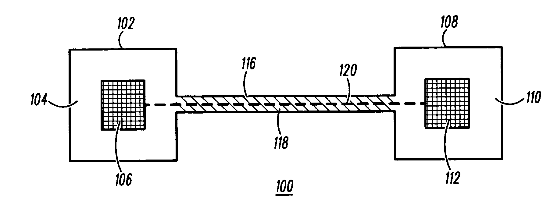
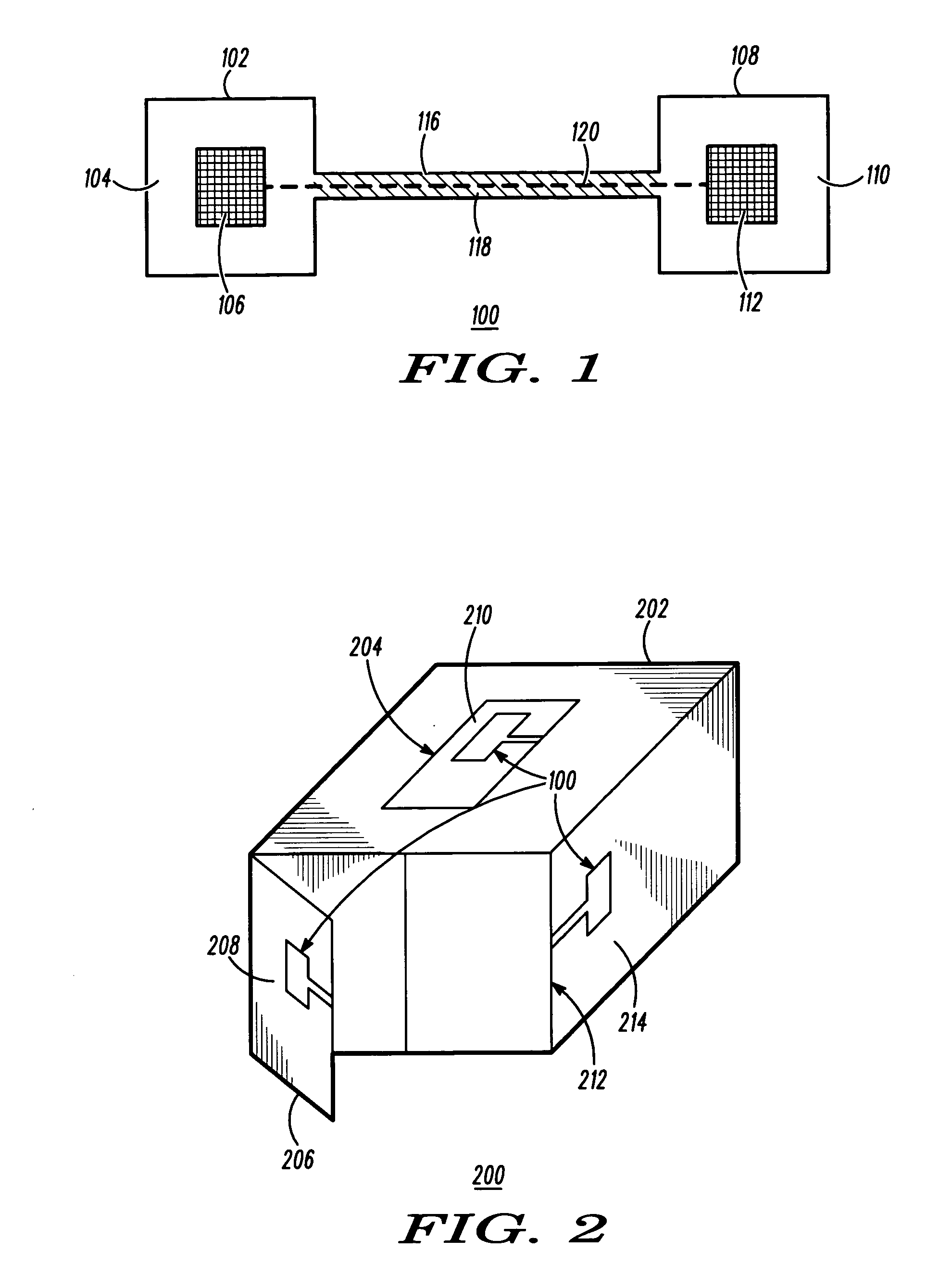
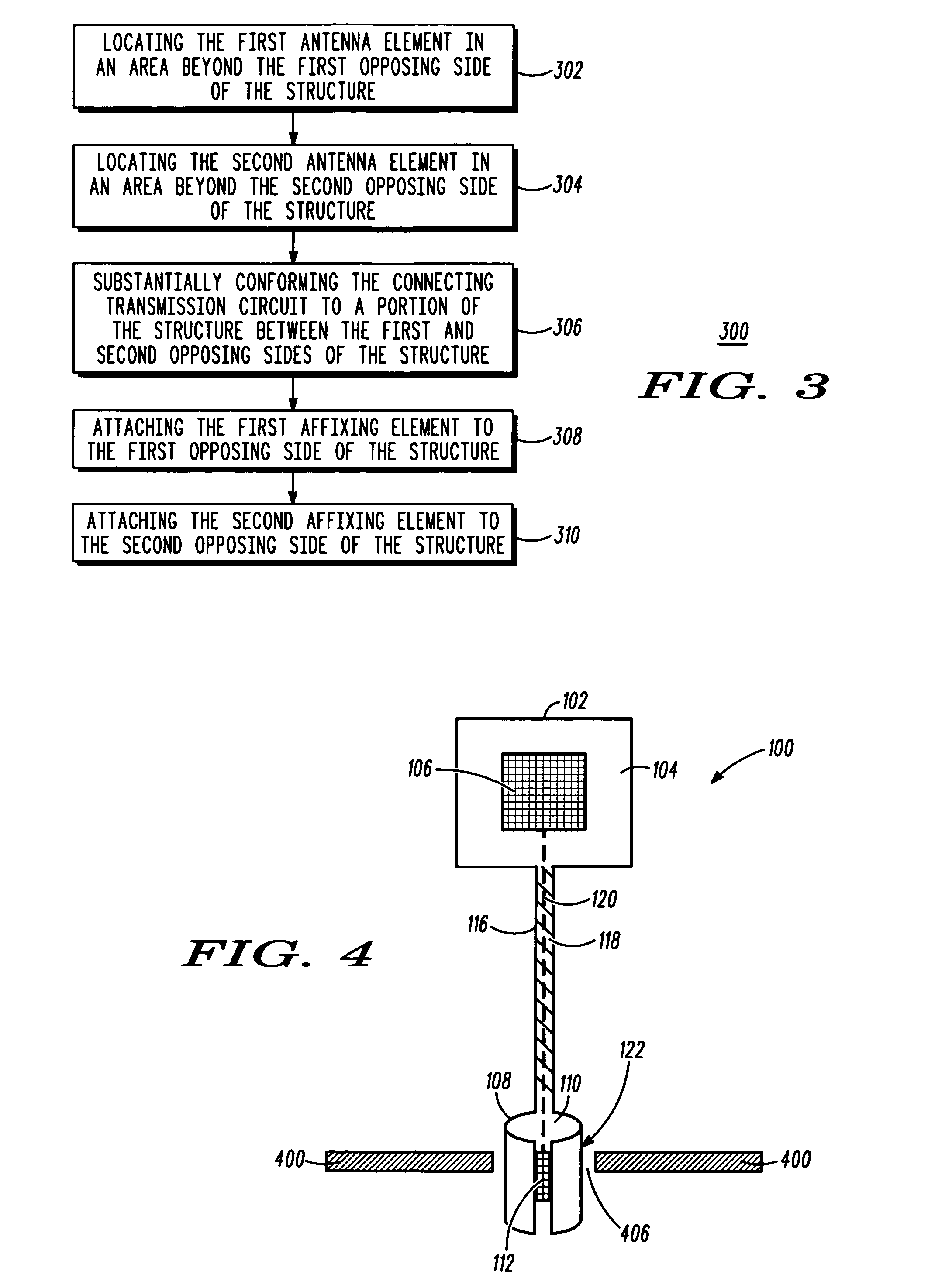
A passive repeater includes: a connecting transmission circuit having first and second opposing ends and made of a flexible material for substantially conforming to a portion of a structure, the structure having first and second opposing sides; first and second antenna elements respectively coupled to the first and second opposing ends of the connecting transmission element; and first and second affixing elements respectively coupled to the first and second antenna elements for attaching the first and second antenna elements to the first and second opposing sides of the structure, wherein the first and second antenna elements are operable to transfer a signal from the first opposing side of the structure to the second opposing side of the structure via the connecting transmission circuit.

Description

FIELD OF THE INVENTION [0001] The present invention relates generally to passive repeaters and more specifically to the use of passive repeaters to transfer radio frequency (RF) signals between a transmitter and receiver when a structure is located therebetween that interferes with the transmission of such signals. BACKGROUND OF THE INVENTION [0002] In RF communications, there are instances especially within buildings and in connection with other structures such as walls or containers where these structures create a barrier to the transmission of the RF signals. Many illustrations of such RF shielding may be envisioned. However, two such scenarios will be described by way of illustration only. [0003] First, the use of RF identification and wireless sensor technology is spreading in the supply chain and transportation industries. Goods equipped with RF tags and sensors are nested within larger containers for transport. Typical inter-modal cargo containers are constructed with steel t...

Claims


Application Information

Patent Timeline
IPC IPC(8): H01Q1/38
CPCH01Q1/007H01Q9/0407H01Q1/38B66B1/3461
Inventor BURIS, NICHOLAS E.RACHWALSKI, RICHARD S.TURNEY, WILLIAM J.
Owner MOTOROLA SOLUTIONS INC
Learn More