Transmitting apparatus and transmitting method

a technology of transmitting apparatus and transmitting method, which is applied in the direction of digital output to print units, data switching networks, instruments, etc., can solve the problems of inability to deal with such trouble, troublesome destination who has received the wrong transmission, and inability to transmit image data

Active Publication Date: 2007-09-06
SHARP KK
View PDF2 Cites 7 Cited by
  • Summary
  • Abstract
  • Description
  • Claims
  • Application Information

AI Technical Summary

Benefits of technology

[0019]The transmitting apparatus according to the invention is provided with detecting means for detecting that the line of a destination is busy. When the line of the destination is busy, the deletion of destination information including the destination is not made. In this invention, the detecting means detects that the line of a destination is busy; when the line of the destination is busy, the deletion of destination information including the destination is not made. Therefore it is possible to eliminate cases where destination information is deleted b

Problems solved by technology

However, when wrong destination information is registered and stored, image data cannot be transmitted and a destination who has received the wrong transmission is troubled.
For example, when a piece of registered destination information is not a FAX number but a telephone number, a sender's apparatus (such as a digital multifunction machine

Method used


Image

  • Transmitting apparatus and transmitting method
  • Transmitting apparatus and transmitting method
  • Transmitting apparatus and transmitting method

Examples


Embodiment Construction

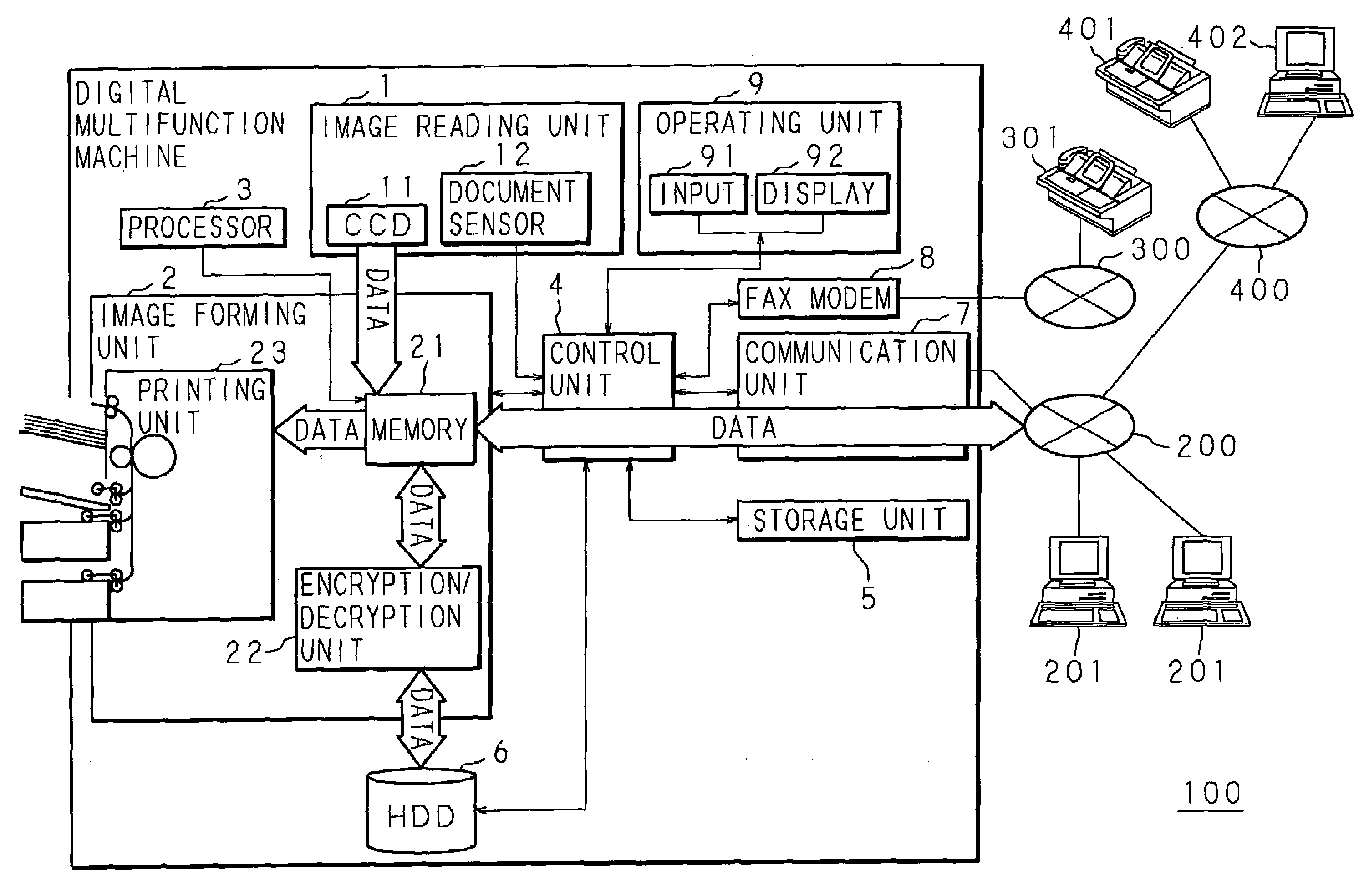
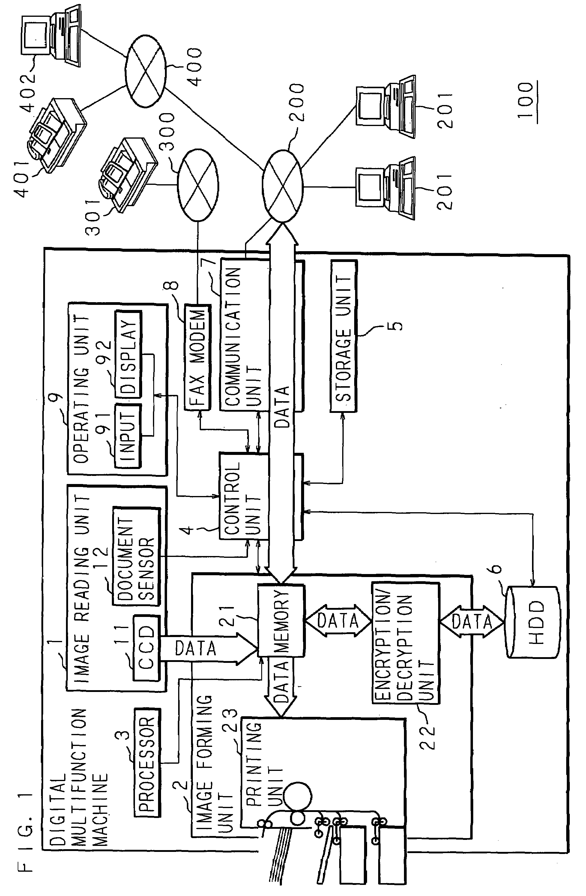
[0034]An embodiment according to the present invention will be described below in detail with reference to the accompanying drawings. FIG. 1 is a block diagram of an internal configuration of a digital multifunction machine 100 provided with a transmitting apparatus according to the invention. As shown in FIG. 1, the digital multifunction machine 100 is provided with an image reading unit 1, an image forming unit 2, a processor 3, a control unit 4, a storage unit 5, a HDD 6, a communication unit 7, a FAX modem 8, and an operating unit 9, and so on.

[0035]The image reading unit 1 is provided with a CCD 11, a document sensor 12, and so on. At the image reading unit 1, a document placed on a document feeder tray is sensed by the document sensor 12 and then irradiated with light while being conveyed along a conveying path by means of an automatic document feeder (ADF). Thereafter, reflected light from the document is photoelectrically converted by the CCD 11 into an analog signal, follow...


PUM


Abstract

When a transmission of image data to a destination has not been completed, retransmission processing in which the image data is repeatedly transmitted to the destination is performed and the number of times the transmission has been performed is counted. When the number is higher than a predetermined value, the sender is informed about the occurrence of transmission error and whether the modification of destination information has been requested is determined. When the modification has been requested, the destination information is modified; when the modification has not been requested, the destination information is deleted and then the deletion of the destination information is informed. When stored destination information including destinations of data is wrong, the use of the destination information is inhibited, which prevents users as recipients from feeling displeasure.

Description

CROSS-REFERENCE TO RELATED APPLICATION[0001]This Nonprovisional application claims priority under 35 U.S.C. §119(a) on Paten Application No. 2006-56585 filed in Japan on Mar. 2, 2006, the entire contents of which are hereby incorporated by reference.BACKGROUND OF THE INVENTION[0002]The present invention relates to a transmitting apparatus provided with a one-touch dialing function capable of storing information on the destinations of data in advance, eliminating the input of the destination information done every time transmissions are made, and simplifying transmitting operations and to a transmitting method for the apparatus.[0003]With the recent enhanced speed of information processing and increased amount of information as epitomized by the Internet, digital multifunction machines, facsimile machines, or the like having scanner function, printer function, facsimile function, mail transmitting function, and so on have been connected with information communication terminals such a...

Claims


Application Information

Patent Timeline
IPC IPC(8): H04L12/66
CPCH04N1/32074H04L1/1803
Inventor UEDA, SUEHIROYOSHIURA, SYOICHIROYOSHIMOTO, TSUTOMU
Owner SHARP KK
Why Eureka
Try Eureka