Retractor illumination system

a technology of illumination system and retractor, which is applied in the field of retractor illumination system, can solve the problems of interference with illumination, changes in patient or surgeon, and numerous limitations of traditional overhead lighting system

Active Publication Date: 2007-09-06
INVUITY
View PDF100 Cites 133 Cited by
  • Summary
  • Abstract
  • Description
  • Claims
  • Application Information

AI Technical Summary

Benefits of technology

[0006] An alternate medical retractor illumination system may include a light guide retractor having a distal end, a proximal end, an upper surface and a lower surface, the lower surface is adapted to engage tissue to expose a surgical field, the light guide retractor having an input adapter and one or more light emitting surfaces to illuminate the surgical field, and a light source providing illumination energy to the input adapter.
[0007] Anot

Problems solved by technology

Traditional overhead lighting systems include numerous limitations.
Changes in patient or surgeon positioning may interfere with the illumination.
Frequent adjustments are an inconvenience for the surgeon and disrupt the surgical flow.
Overhead lighting is frequently inadequate for surgery in deeper cavities where more intense focused illumination may be required.
In addition, the alignment of the surgeons head frequently interferes with the remote illumination and prevents light from reaching the field.
However, these devices also have numerous limitations.
First, the surgeon is tethered by the light cord attached to the headset, limiting mobility in the operating room.
S

Method used


Image

  • Retractor illumination system
  • Retractor illumination system
  • Retractor illumination system

Examples


Embodiment Construction

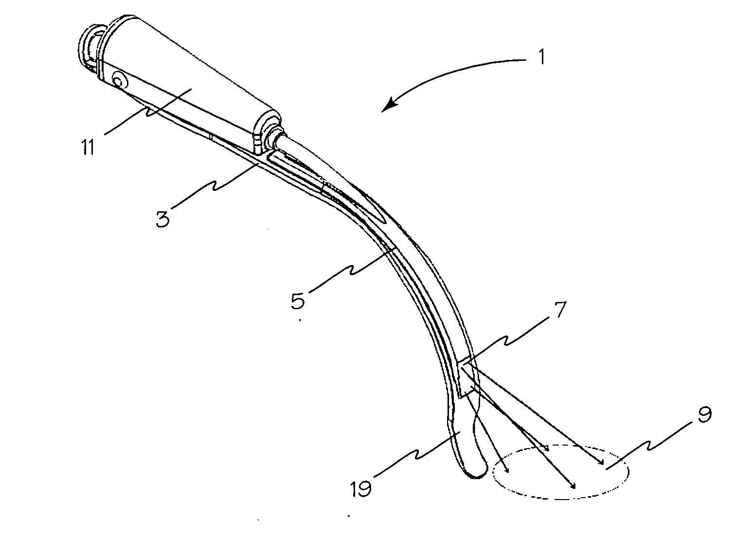
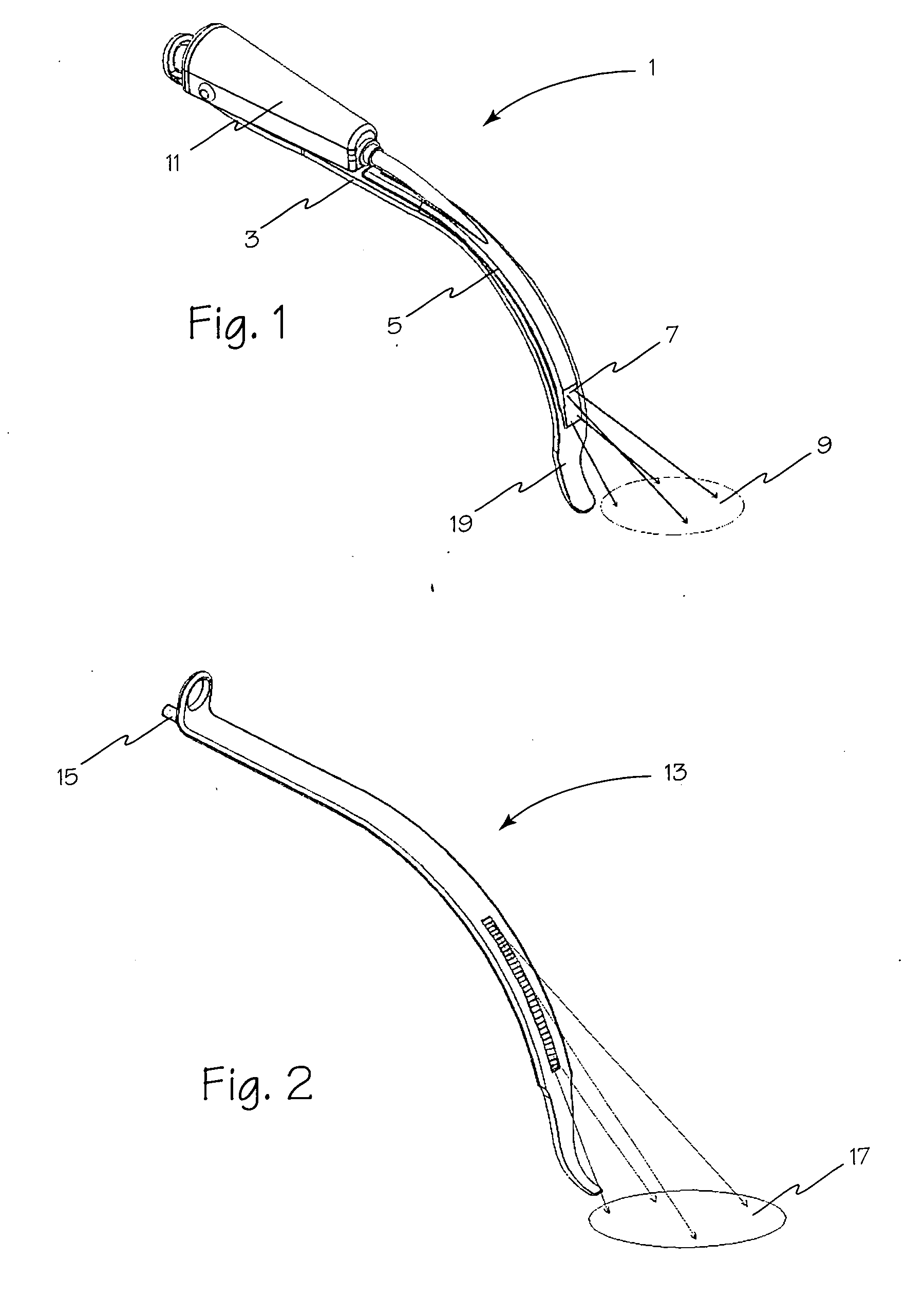
[0029]FIGS. 1 and 2 illustrate a retractor illumination system implemented by modification of a typical retractor. In FIG. 1, retractor 3 is fitted with a light guide insert 5 which is mounted on the retractor, such that a light emitting surface 7 of the light guide faces the open surgical field 9. The light guide insert 5 may be mounted on the field surface of the retractor, or it may be mounted on the back side of the retractor, so long as a light emitting portion 7 of light guide 5 is exposed to illuminate surgical field 9, for example, through a cut out formed in the retractor or from around one or more sides of the retractor. Light guide insert 5 of FIG. 1 may be formed of any suitable material such as transparent or translucent material, shaped to conform to the surface of retractor 3 and includes one or more mating structures for releasable or fixed attachment to the retractor. A light source 11 may be mounted on the distal end of the retractor, in optical communication with ...


PUM


Abstract

An apparatus for the efficient provision of directed illumination to a subdermal surgical field that is attachable to or completely forms a surgical retractor blade.

Description

RELATED APPLICATIONS [0001] This application claims priority to co-pending U.S. provisional patent application 60 / 760,167 filed Jan. 18, 2006.FIELD OF THE INVENTIONS [0002] The inventions described below relate to the field of illumination of tissue and surgical work space within the body during surgery, especially during minimally invasive surgery. BACKGROUND OF THE INVENTIONS [0003] Existing technology for illumination during surgical / medical procedures is generally overhead illumination. This illumination comes from either raised fixtures above the surgical field or head mounted fiber optic systems. Traditional overhead lighting systems include numerous limitations. Direct exposure of the field from the overhead source is required. Changes in patient or surgeon positioning may interfere with the illumination. Frequent adjustments are an inconvenience for the surgeon and disrupt the surgical flow. Overhead lighting is frequently inadequate for surgery in deeper cavities where more...

Claims


Application Information

Patent Timeline
IPC IPC(8): A61B1/32
CPCA61B17/02A61B1/32A61B1/06A61B2019/5206A61B2090/306
Inventor GREY, THOMASVAYSER, ALEXGASSON, JON
Owner INVUITY
Why Eureka
Try Eureka