
Shaped retractor blade

a retractor blade and shaped technology, applied in the field of surgical tools, can solve the problems of non-uniform thickness between tissue contact sides and shaped retractor blades, and achieve the effect of high tensile strength

Inactive Publication Date: 2007-04-12
MINNESOTA SCI
View PDF31 Cites 68 Cited by
  • Summary
  • Abstract
  • Description
  • Claims
  • Application Information

AI Technical Summary

Benefits of technology

[0008] The present invention is a shaped surgical retractor blade, and a retractor assembly using the shape retractor blade. In contrast to prior art retractor blades, the shaped retractor blade is not formed of sheet material but rather has a non-uniform thickness between the tissue contacting side and the surgical arena side. In one aspect, the tissue contacting side of the blade has a convex curvature, and the non-uniform thicknes

Problems solved by technology

In contrast to prior art retractor blades, the shaped retractor blade is not formed of sheet material but rather has a non-uniform thickness between the tissue contacting side and the surgical arena side.

Method used


Image

  • Shaped retractor blade
  • Shaped retractor blade
  • Shaped retractor blade

Examples


Embodiment Construction

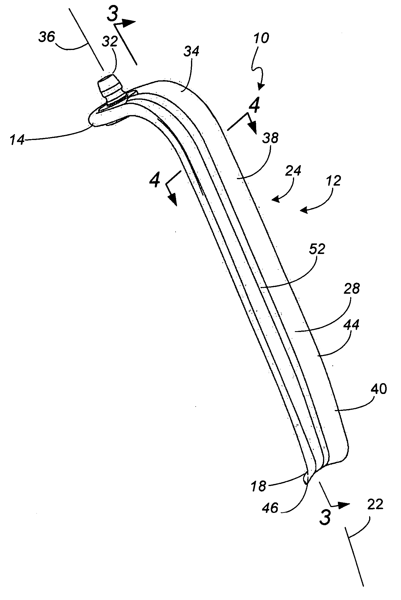
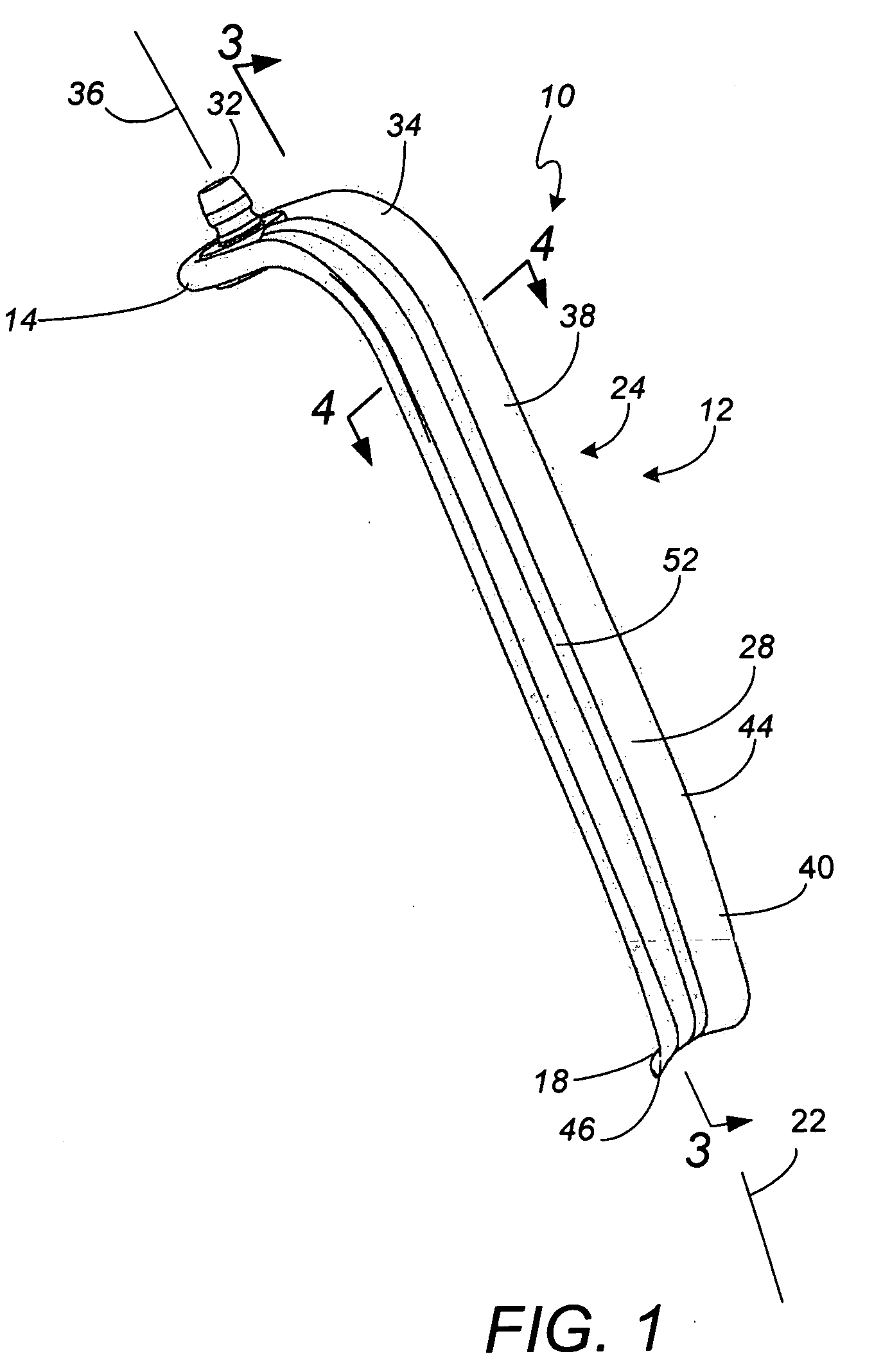
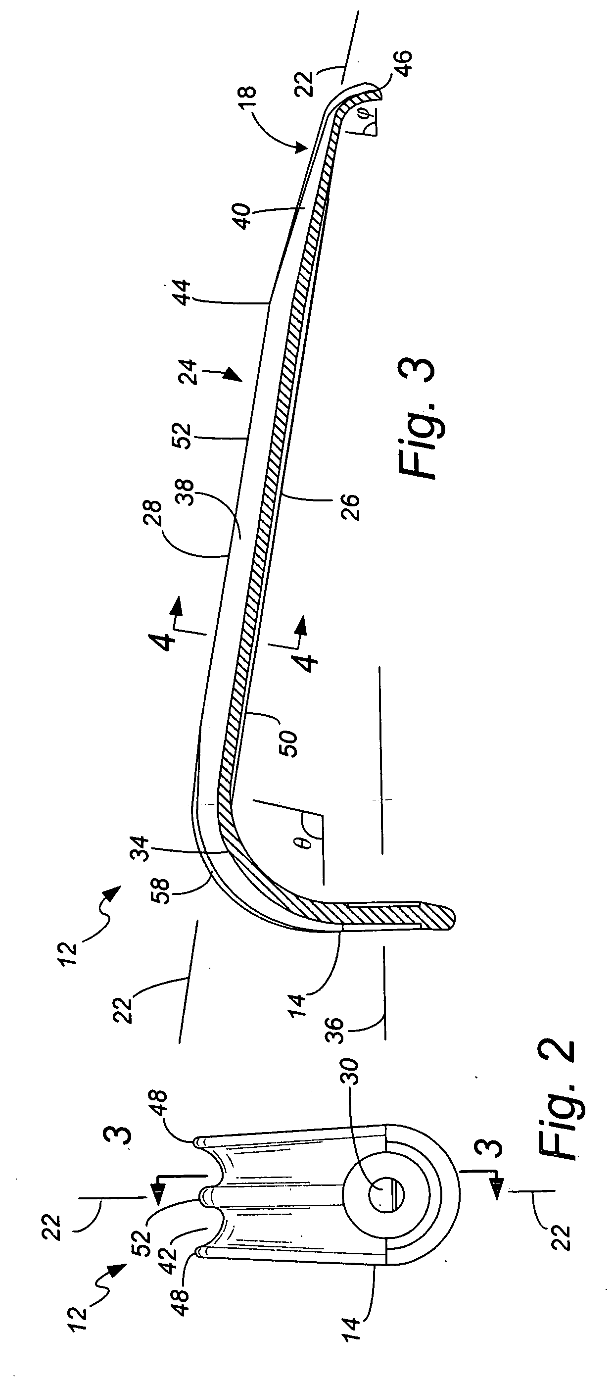
[0027] A first embodiment of a shaped surgical retractor blade 10 in accordance with the present invention is shown in FIGS. 1-4. This particular embodiment is a renal vein blade 10, having a blade width of about ⅞th inch and a blade length of about six inches. The blade 10 has a blade body 12 with a proximal end 14 for attachment as part of a retractor assembly 16 (shown further in FIG. 5). The blade body 12 has an opposing distal end 18 which extends into the surgical incision 20 (as shown in FIG. 5). In the preferred embodiment, the retractor blade 10 is symmetrical about a longitudinal bisecting plane which includes a longitudinal axis 22. Between the proximal and distal ends 14, 18, the blade body 12 includes an extending portion 24. The extending portion 24 for the preferred renal vein blade 10 extends generally linearly when depicted in longitudinal cross-section as shown in FIG. 3, providing the length of the blade 10. It is noted that the invention can be equally applied to...


PUM


Abstract

A shaped surgical retractor blade is used in a surgical retractor assembly. The shaped retractor blade is not formed of sheet material but rather is formed to have a non-uniform thickness between the tissue contacting side and the surgical arena side. The non-uniform thickness can be provided by a longitudinally running rib running between two recesses on surgical arena side of the retractor blade. The recesses provide openings through which the surgeon can better view the surgical arena. The rib provides additional bending strength to the retractor blade. The tissue contacting side of the blade can have a convex curvature, minimizing the possibility of tissue damage at the location that the blade contacts the tissue. The retractor blade can have a constant longitudinally extending section and a distal, tapering section. The uniquely shaped retractor blade can be formed, for instance, such as by injection molding a high tensile strength polymer material which provides desired optical / fluoroscopic / magnetic resonance imaging properties.

Description

CROSS-REFERENCE TO RELATED APPLICATION(S) [0001] None. BACKGROUND OF THE INVENTION [0002] The present invention relates to the field of surgical tools, and particularly to the design and manufacture of surgical retractor systems. Surgical retractor systems are used during surgery to bias and hold tissue in a desired position. As one example, some surgical procedures require anterior access to the spine, through the patient's abdomen. Tissue such as skin, muscle, fatty tissue and interior organs needs to be held retracted to the side so the surgeon can obtain better access to the vertebrae structures of primary interest. [0003] Surgical retraction may be performed by one or more aides using handheld tools, with the most basic retractor apparatus being a tongue depressor. More commonly now in sophisticated operating rooms during abdominal or chest surgery, a surgical retractor system or assembly is used. The retractor assembly may, for instance, include a ring which is rigidly support...

Claims


Application Information

Patent Timeline
IPC IPC(8): A61B1/32
CPCA61B17/02A61B2017/00526A61B2017/00902
Inventor LEVAHN, STEVENVON WALD, RONALD
Owner MINNESOTA SCI
Learn More