Variably flexible insertion device and method for variably flexing an insertion device

Inactive Publication Date: 2007-09-06
SYNTHEON
60 Cites 79 Cited by

AI-Extracted Technical Summary

Problems solved by technology

The Ewers et al. and Sturges devices are complicated and have only elastic tension wires or a flexible cable to main...

Method used

[0050]FIG. 10 also shows the friction locking pads 25, the inner handle 30 with the grooves 10 and the tendons 11 passing through the grooves 10 and under the fifth vertebra 17. The cross section of the vertebra 17 illustrated in FIG. 15 additionally shows a coil 36 of the hollow body disposed within and supporting the inner sleeve 35. The coil may be a wire which is TEFLON- or hydroph...

Benefits of technology

[0019] Therefore, according to the invention, both a transitioning device using a vacuum to cause contact between the inner and outer sleeves and tendons supporting the stiffening but being free of tensio...

Abstract

A variably flexible insertion device includes a hollow body having a proximal end with an entrance for receiving an instrument and a distal end with a tip for protrusion of the instrument. A device transitions the hollow body between a relatively flexible condition and a relatively stiff condition. Tendons within the hollow body maintain the hollow body in the relatively flexible and relatively stiff conditions. A method for variably flexing an insertion device for receiving an instrument, includes providing a hollow body having inner and outer sleeves defining a space therebetween in which tendons are disposed. Suction is applied to create a vacuum in the space for frictionally locking the tendons in place between the sleeves in a relatively stiff condition of the hollow body. The vacuum is relieved to release the tendons in a relatively flexible condition of the hollow body.

Application Domain

Technology Topic

EngineeringInsertion device +2

Image

  • Variably flexible insertion device and method for variably flexing an insertion device
  • Variably flexible insertion device and method for variably flexing an insertion device
  • Variably flexible insertion device and method for variably flexing an insertion device

Examples

  • Experimental program(1)

Example

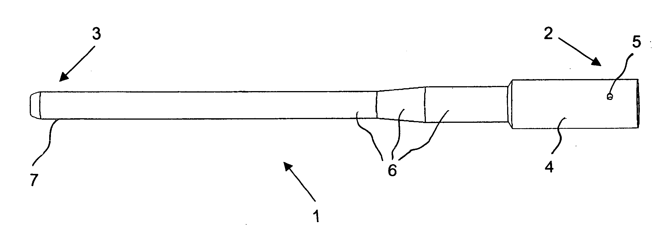
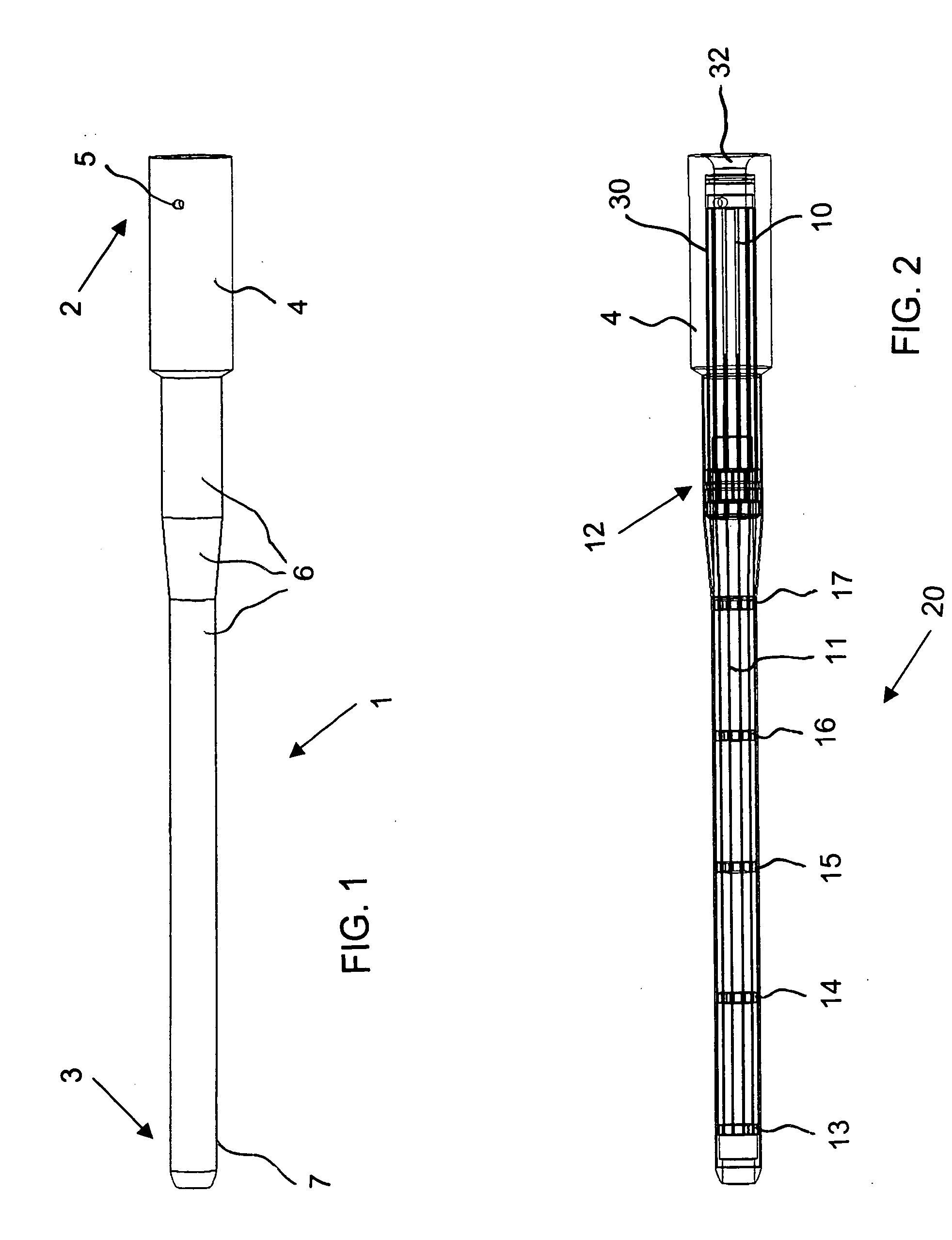
[0043] Referring now to the figures of the drawings in detail and first, particularly, to FIG. 1 thereof, there is seen a variably flexible insertion device 1 according to the invention. The insertion device 1 has a hollow body with a proximal end 2 for manipulation by an operator and for receiving an instrument 32 such as an endoscope or colonoscope seen in FIG. 5. The insertion device 1 also has a distal end 3 for insertion into a patient and for protrusion of the instrument 32. An outer handle 4 of the hollow body for the operator is disposed at the proximal end 2. The handle 4 has a vacuum port 5 formed therein. An outer sleeve 6 of the hollow body is disposed between the outer handle 4 and a nose tip 7 of the hollow body at the distal end 3. The outer sleeve 6 provides a flexible section with a given length extending beyond the handle 4.
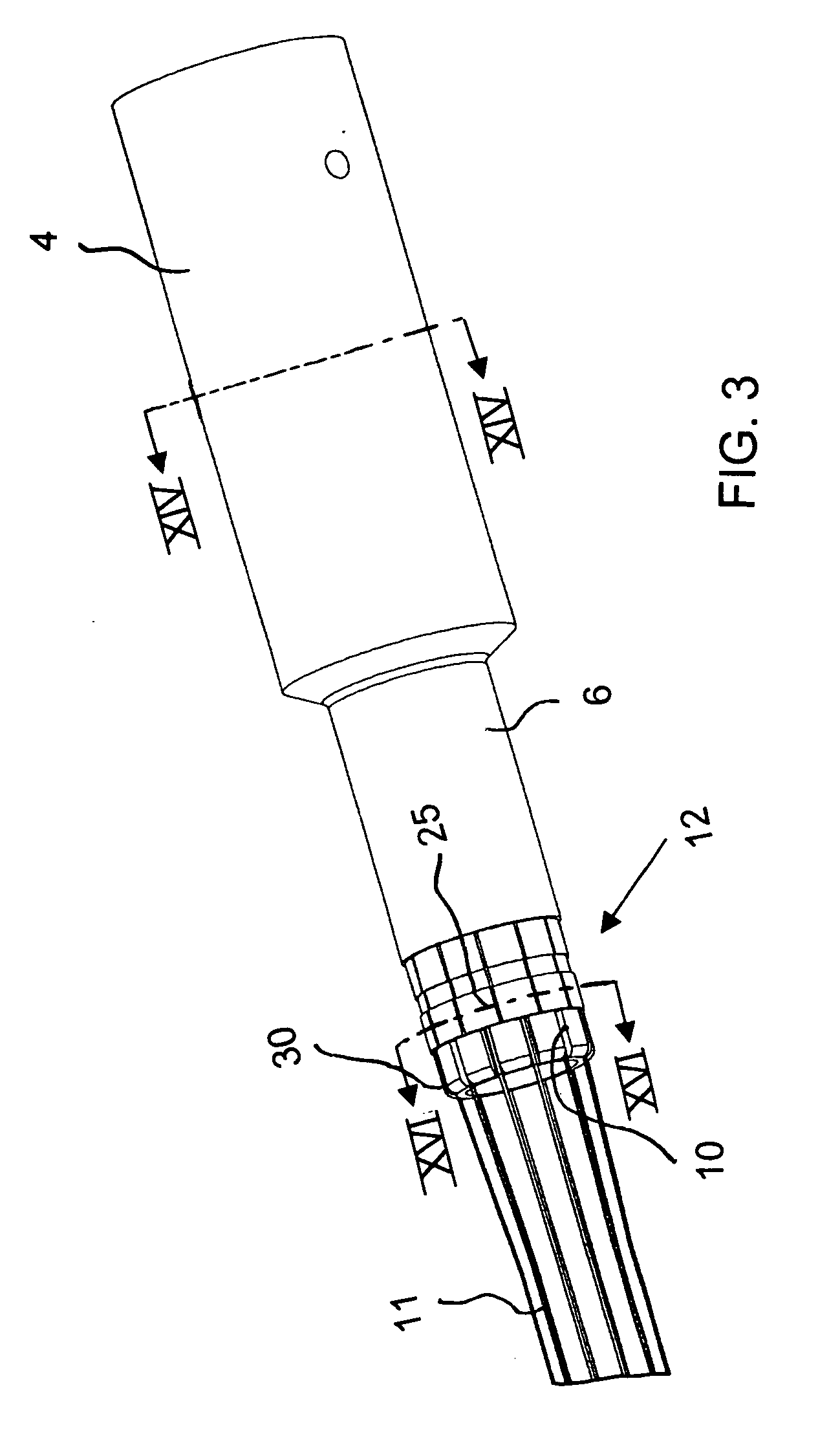
[0044]FIG. 2 shows that the outer handle 4 contains an inner handle 30 of the hollow body having channel grooves 10 which permit movement of tendons 11. The tendons 11 extend substantially entirely over the given length of the flexible section provided by the outer sleeve 6. The tendons 11 may have a rounded or flattened cross section or a flattened cross section twisted along its length. A friction lock area 12 is disposed within the outer sleeve 6 for locking the tendons 11 in a manner to be discussed below. Vertebrae 13-17 are distributed along a flexible area 20 which is approximately 30 inches long. Whereas the vertebrae 14-17 allow movement of the tendons 11, the first vertebra 13 closest to the distal end 3 is fixed to the tendons 11. Although six vertebrae are shown, it is understood that more or fewer vertebrae may be provided, for example eight vertebrae, depending on the length of the device 1. The number of tendons 11 is also variable, although twelve is used as an example.
[0045] As is seen in FIG. 3, a ring of locking pads 25 encircles the friction lock area 12. Each tendon 11 is assigned a respective locking pad 25, which is clearly shown in FIG. 16. The tendons 11 are disposed between the locking pads 25 and a friction surface 26 shown in FIGS. 4 and 16. The friction surface 26 is part of the inner handle 30 having the grooves 10 in which the tendons 11 move.
[0046]FIG. 5 illustrates the outer handle 4 as well as the inner handle 30 with the channel grooves 10 for the tendons 11. The outer handle 4 is shown as being transparent in FIG. 5, so as to be able to illustrate an entrance 32 for the surgical instrument 38, such as an endoscope or colonoscope, a groove 33 for receiving an O-ring and the vacuum port 5.
[0047]FIG. 6 shows the region of the nose tip 7. The tendons 11 are fixed and welded to the first vertebra 13. FIG. 7 also shows the tendons 11 fixed to the first vertebra 13 as well as the second vertebra 14 under which the tendons are free to move in the channel grooves 10 formed in the inner handle 30.
[0048] The sectional view of FIG. 8 illustrates the outer sleeve 6, the nose tip 7, two tendons 11, as well as the tendons being welded to the first vertebra 13 and being freely movable in the second vertebra 14. An inner sleeve 35 of the hollow body is also shown in FIG. 8. FIG. 8 additionally shows an end cap 37 to be snapped-on at the distal end to accommodate different sized instruments or scopes 38.
[0049]FIG. 9 shows how the tendons 11 are freely movable in the channel grooves 10 in the inner handle 30 and pass over the friction surface 26.
[0050]FIG. 10 also shows the friction locking pads 25, the inner handle 30 with the grooves 10 and the tendons 11 passing through the grooves 10 and under the fifth vertebra 17. The cross section of the vertebra 17 illustrated in FIG. 15 additionally shows a coil 36 of the hollow body disposed within and supporting the inner sleeve 35. The coil may be a wire which is TEFLON- or hydrophilic-coated to ease insertion of an endoscope or colonoscope. The stiffness or spring constant k of the coil 36 tends to maintain the device 1 in a straight condition. However, as will be explained in detail below, the device 1 does not remain straight when held horizontal in its flexible state. The coil 36 is used to maintain the round cross section of the device 1 while it is flexed.
[0051] The view of FIG. 11 shows the tendons 11 passing through the channel grooves 10 formed in the inner handle 30 and under the friction locking pads 25. The tendons 11 are freely movable in the channel grooves 10, except when pinched between the friction locking pads 25 and the friction surface 26 in the friction lock area 12.
[0052] The cross-sectional view of FIG. 12 shows an O-ring 31 disposed in the groove 33. FIG. 14 shows a space 34 between the outer handle 4 and the inner handle 30. The space 34 is sealed by the O-ring 31 and communicates with the vacuum port 5 for applying positive and negative pressure (vacuum) to the space.
[0053]FIG. 13 is a cross-sectional view illustrating details of the friction lock area 12. It may be seen that the tendons 11 which pass below the vertebrae 16, 17 are pinched between the friction locking pads 25 and the friction surface 26 in the friction area 12.
[0054] According to another embodiment of the invention which is illustrated in FIG. 18, the hollow body 4, 6, 7, 30, 35, 36 has a longitudinal slit 39 formed therein for radially loading the hollow body onto the instrument 38. The slit has a closure 40, such as a slide or press zipper used for plastic storage bags, permitting the device to be resealed after the hollow body has been loaded. The coil in this case is a ring wire, double wire, double loop or twin loop binding 41 seen in FIG. 19, such as is used for notebooks.
[0055] The operation of the variably flexible insertion device 1 is best understood by making reference to FIG. 17 in conjunction with the above-described figures. After the device 1 is forced into a flexed condition against the stiffness or spring constant k of the coil 36 as seen in FIG. 17, for example upon traversing the rectosigmoid junction, and it is desired to maintain that flexed condition for guiding an endoscope, such as a colonoscope, vacuum is applied to the space 34 through the vacuum port 5. When suction is applied to create the vacuum, it causes the inner sleeve 35 and the outer sleeve 6 to firmly contact each other with the tendons 11 sandwiched and frictionally locked therebetween. Therefore, the vacuum port 5 acts as a device for transitioning the hollow body 4, 6, 7, 30, 35, 36 between the relatively flexible condition and the relatively stiff condition through the application of a vacuum. Most of the stiffness causing the device 1 to maintain its flexed condition is accomplished by this interaction of the inner and outer sleeves and the tendons. However, additional stiffness may optionally be accomplished by providing the friction locking pads 25 which contract and hold the tendons 11 against the friction surface 26 in the friction area 12. The device 1 therefore maintains its flexed condition. FIG. 17 shows that in the flexed condition, the tendons 11 at the outer periphery of the bend become shorter and the tendons 11 at the inner periphery of the bend become longer, since they are all fixed in place at the first vertebra 13.
[0056] The tendons or wires 11 are passive elements which are not in tension at any time. The tendons float within the hollow body when it is in the flexible condition, except at the distal end. The tendons are frictionally locked by the inner sleeve 35 and the outer sleeve 6 when the hollow body is in the stiff condition. However, in both the relatively flexible condition and the relatively stiff condition, the tendons have no active control imposed on them and are not pulled or constrained.
[0057] When it is desired to resume flexibility of the device 1, the vacuum in the space 34 is replaced by air at ambient or positive pressure. This causes the inner sleeve 35 and the outer sleeve 6 to release the tendons 11 and allows the stiffness or spring constant k of the coil 36 to place the device 1 into its normally flexible condition. If friction locking pads 25 are used, they also relax and expand, which in turn releases the tendons 11.
[0058] The device is intended to be used in a manner similar to prior art devices. Therefore, the device will be placed over the endoscope. The endoscope will then be inserted into the rectum. The device will then be pushed in its flexible condition, to follow the curvature of the scope. The device will then be stiffened, allowing the scope to be pushed forward with less pressure exerted on the colon of the patient. This procedure can be repeated until the scope reaches the cecum.
[0059] An alternative use of the device is to aid in small bowel endoscopy. The device is placed over the endoscope. The endoscope is inserted into the patient transorally, through the stomach and then partially into the small bowel. The device is then pushed in its flexible condition, to follow the curvature of the scope. The device is then stiffened, allowing the scope to be pushed forward without the scope looping in the stomach.
[0060] Another use of the device is for aiding in access to internal body parts, such as the gallbladder, through an opening of an internal body cavity, such as the stomach. The device is placed over the endoscope. The endoscope is inserted into the patient transorally, through the stomach and then up against the internal surface of the stomach. The device is then pushed in its flexible condition, to follow the curvature of the scope. The device is then stiffened, allowing the surgeon to create an opening in the stomach wall without the scope looping in the stomach. Once the opening is created, the device and the scope can be advanced outside the stomach. The device can then be stiffened to create a stable platform to perform surgical procedures outside of the stomach. The device could contain one or more features (i.e. balloons) for sealing the outer periphery of the device to the stomach wall to prevent gastric fluids from exiting the stomach.
[0061] According to the other embodiment of the invention, the device is capable of being loaded on the instrument or scope after the scope is inserted into the patient. In this embodiment, the slit down the length of the device allows it to be loaded on the scope so that the scope is inserted radially into the hollow body.

PUM

no PUM

Description & Claims & Application Information

We can also present the details of the Description, Claims and Application information to help users get a comprehensive understanding of the technical details of the patent, such as background art, summary of invention, brief description of drawings, description of embodiments, and other original content. On the other hand, users can also determine the specific scope of protection of the technology through the list of claims; as well as understand the changes in the life cycle of the technology with the presentation of the patent timeline. Login to view more.

Similar technology patents

Classification and recommendation of technical efficacy words

Why Eureka
Try Eureka