
Removable Device for Attaching Two Mechanical Parts

Active Publication Date: 2007-09-13
METALOGENIA SA
View PDF9 Cites 16 Cited by
  • Summary
  • Abstract
  • Description
  • Claims
  • Application Information

AI Technical Summary

Benefits of technology

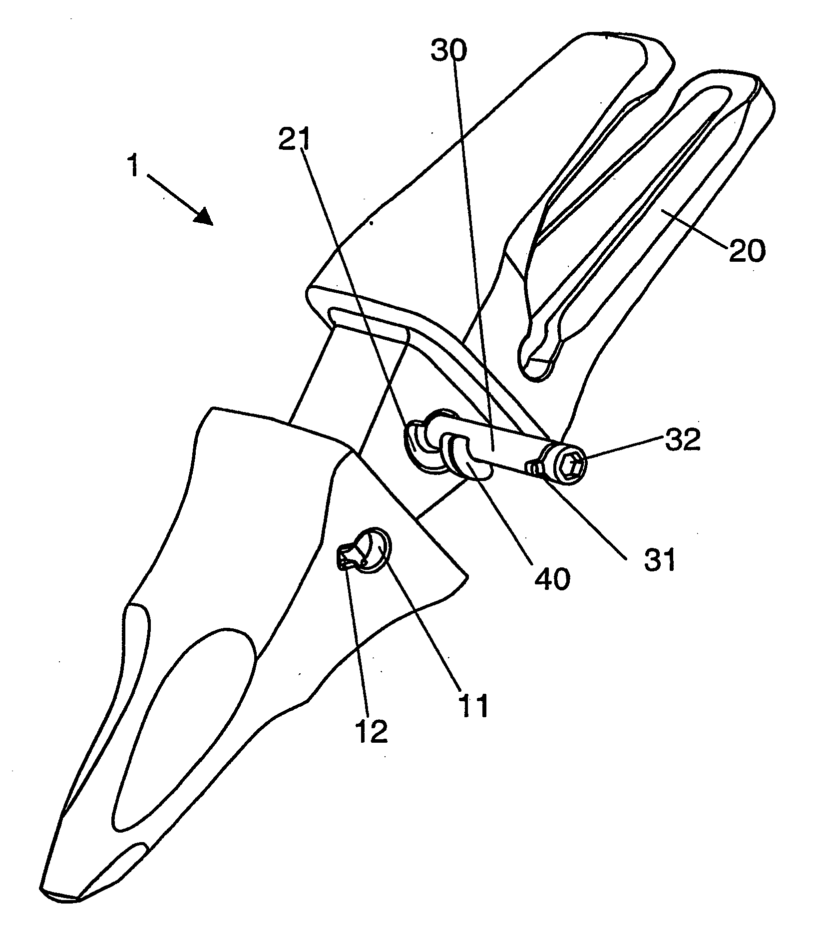
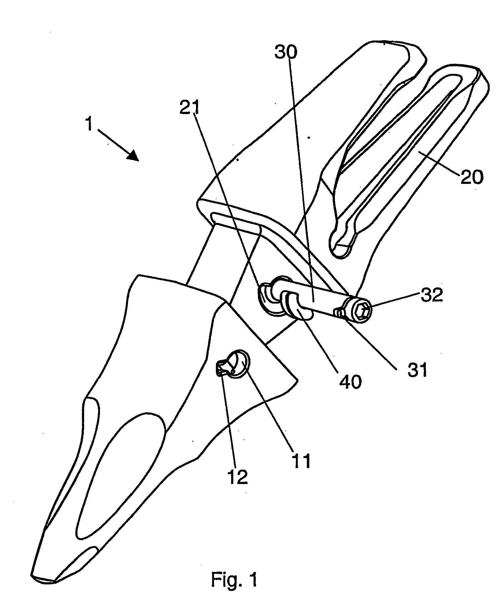
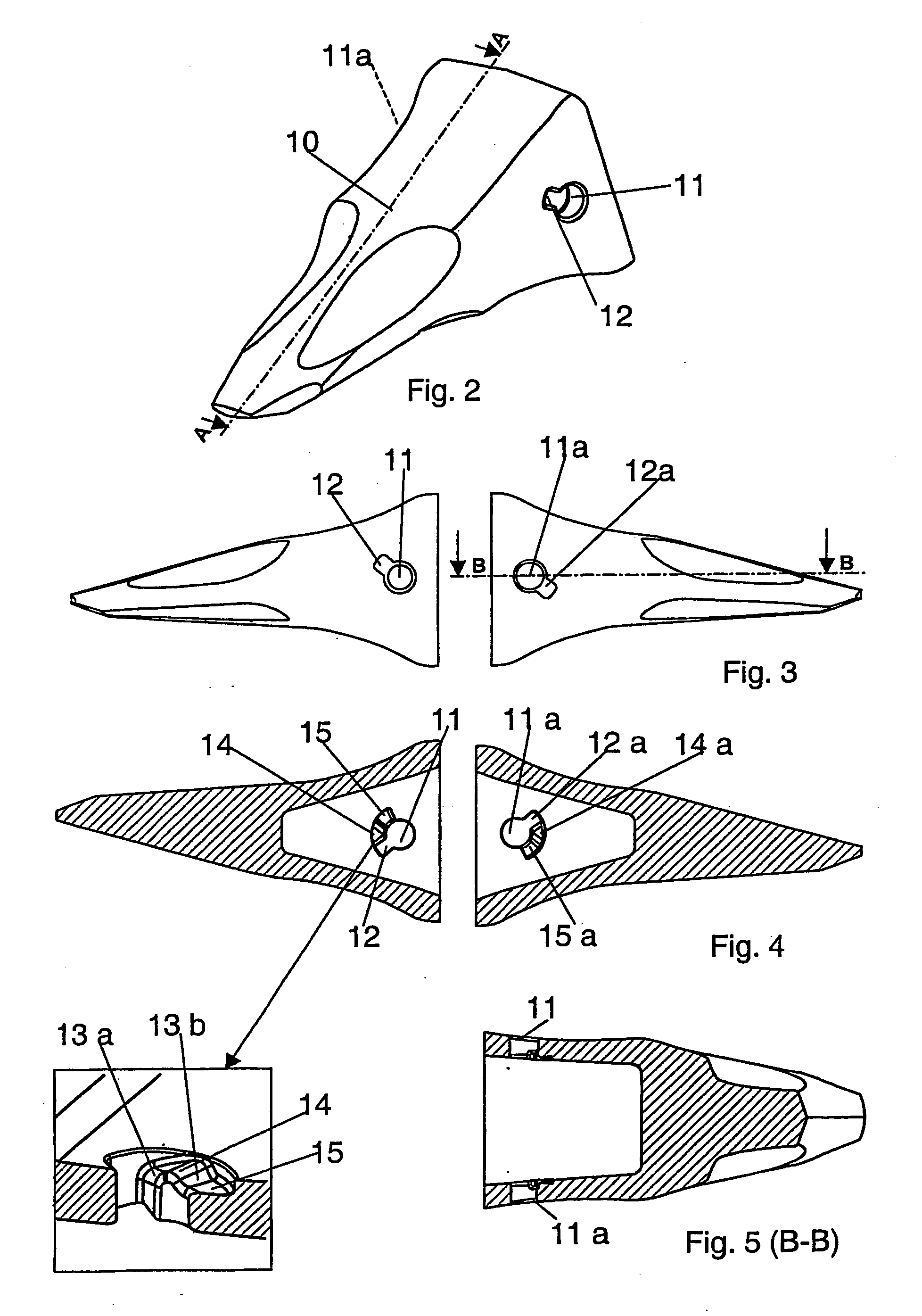
[0008] In order to overcome the drawbacks mentioned and to simplify the assembly and removal of a tooth in a tooth bar, and more generally of two mechanical parts, one female and the other male, from one another, the attachment device according to the present invention is characterized by the fact that it further comprises at least two inclined planes, the general shape of which is that of a projection oriented in the axial direction of the pin, such that when the pin is rotated, the retainer member runs along said inclined planes and the pin moves between two positions, the pin lock position and the unlock or introduction position, against the force axial to the pin exerted by said tension member. Said retainer member has four, two-by-two parallel faces, the two upper and lower faces being the ones which allow exerting the pressure on the tension member as well as facilitating the sliding of the retainer member, and therefore the rotation of the pin, in order to reach the lock position.

Problems solved by technology

However, said blades are also subjected to wear and breaks, whereby they must often be replaced and furthermore, depending on the work which the machine is to perform, it may be desirable to change the type or shape of the teeth.
When the usual arrangements operate under difficult conditions, the pin has the tendency to be displaced against the pushing force of the retainer device.
Then the pin can come out of the tooth bar, the pin and tooth possibly being lost.
The loss of a tooth and / or pin may be very important according to the operating site thereof, such as mines or quarries for example, since they may damage other machines, such as crushers, operating in the same production site as the machine using the tooth.
This requirement of striking the pin in order to fit it into the washer is evidently uncomfortable and arduous since it is usually necessary to strike the pin horizontally, a difficult operation since the space between tooth bars located on the blade of a bucket is limited, requiring the use of auxiliary tools which only make the assembly and removal of the pin more difficult, increasing the risk of an accident for the operator or operators.
The recess existing in the pin for inserting the washer likewise weakens the pin, the latter possibly breaking due to the work carried out by the tooth-tooth bar assembly and the stress concentration in said recess.
This arrangement entails great complexity for the pin, since it incorporates two moving parts housed and retained in respective cavities of the body of the pin and resiliently loaded by means of coil springs, which negatively affects its production cost.
Furthermore, the moving parts and resilient springs housed in the pin are highly susceptible to being affected by the accumulation of dust and earth, which combined with moisture can form a clay-type paste which may lock the springs and the movement possibilities of the moving parts when it dries, which entails the need to destroy them by hammering when it is necessary to remove the teeth.
In this type of systems, the stresses required for removal exceed assembly stresses since in addition to the difficulties of the design and construction, removal is affected because during operation, the pin and retainer member may become deformed and earth can additionally be introduced in the housing of the pin, making its extraction difficult.

Method used


Image

  • Removable Device for Attaching Two Mechanical Parts
  • Removable Device for Attaching Two Mechanical Parts
  • Removable Device for Attaching Two Mechanical Parts

Examples


Embodiment Construction

[0008] In order to overcome the drawbacks mentioned and to simplify the assembly and removal of a tooth in a tooth bar, and more generally of two mechanical parts, one female and the other male, from one another, the attachment device according to the present invention is characterized by the fact that it further comprises at least two inclined planes, the general shape of which is that of a projection oriented in the axial direction of the pin, such that when the pin is rotated, the retainer member runs along said inclined planes and the pin moves between two positions, the pin lock position and the unlock or introduction position, against the force axial to the pin exerted by said tension member. Said retainer member has four, two-by-two parallel faces, the two upper and lower faces being the ones which allow exerting the pressure on the tension member as well as facilitating the sliding of the retainer member, and therefore the rotation of the pin, in order to reach the lock posi...


PUM

PropertyMeasurementUnit
Shapeaaaaaaaaaa
Tensionaaaaaaaaaa

Abstract

The removable device for attaching two mechanical parts comprises a pin removably locking a first part with respect to a second part, a retainer member associated to the pin and a resiliently loaded tension member which collaborate to prevent the pin from coming out of its lock position; it is characterized in that it further comprises at least two inclined surfaces, the general shape of which is that of a projection oriented in the axial direction of the pin, such that when the pin rotates, the retainer member runs along said inclined surfaces and the pin moves between the lock position and unlock position against the force axial to the axis of the pin exerted by said tension member. The assembly and removal of the parts is carried out in a simple manner, but the attachment during operation of the excavator is at the same time secure and reliable.

Description

[0001] The present invention refers to a removable device for attaching two mechanical parts, comprising a pin removably locking a first part with respect to a second part, a retainer member associated to the pin and a resiliently loaded tension member, which collaborate to prevent the pin from coming out of its lock position. BACKGROUND OF THE INVENTION [0002] Excavating machines and the like, such as those used in public works and mining, are used to pull out, move and load earth and stones. These machines are usually provided with a bucket joined to a mechanical arm. The bucket is provided with a beveled lip or blade on a front edge intended for striking against and penetrating the earth and stone mass. It is usual to mount teeth associated to the blade projecting forwardly therefrom to prevent excessive wear of the blade and to aid in penetrating the earth. However, said blades are also subjected to wear and breaks, whereby they must often be replaced and furthermore, depending ...

Claims


Application Information

Patent Timeline
IPC IPC(8): B23P11/00E02F9/28
CPCE02F9/2825E02F9/2841Y10T403/7013Y10T403/7018Y10T29/49947Y10T403/587Y10T403/553Y10T403/7005F16B2200/71E02F9/28E02F9/2833
Inventor LOPEZ ALMENDROS, JOSEPEREZ LADO, FRANCESCTUTO Y FAJA, JOANALONSO FRIJOLA, ESTER
Owner METALOGENIA SA
Learn More