Bearing between components on construction machines

a construction machine and bearing technology, applied in the direction of mechanical machines/dredgers, soil shifting machines/dredgers, mechanical apparatus, etc., can solve the problems of high manufacturing cost, limited maximum reach of the self-propelled excavators, and analogous problems on assembly, so as to reduce wear and noise, enhance the ease of movement of bearings, and high resistance to kinking

Inactive Publication Date: 2011-02-01
CNH BAUMASCHEN
View PDF25 Cites 8 Cited by
  • Summary
  • Abstract
  • Description
  • Claims
  • Application Information

AI Technical Summary

Benefits of technology

[0011]In a practical embodiment of the invention, the bearing points of the first component, forming the back boom, are located on the middle of the bearing tube and the bearing points of the mid boom, forming the second component, are located along-side it on its outer parts. The associated insertion of the upper end of the back boom into the mid boom means that the back boom need no longer have gaps or recesses as in the reverse case, so that it is highly resistant to kinking. This design is very strong overall, as the section of the mid boom inserted over the back boom must then be larger than that of the back boom anyway and its weakening in the vicinity of the accepted back boom is slight, because only the actual angle of movement needs to be unobstructed as a fork.
[0012]In a further advantageous embodiment of the invention, the bearing points of the first and secon...

Problems solved by technology

This solution has several disadvantages, namely that the connection between the three components, the back boom, mid boom and boom cylinder by means of the pin must accept the forces from all the components on its own in this embodiment, as a result of which it must have a correspondingly large diameter.
However, a large diameter of the bearing point for the bosses of the boom cylinder means that the stroke of the boom cylinder and thus the maximum reach of the boom of the self-propelled excavator would be restricted.
As this would...

Method used


Image

  • Bearing between components on construction machines
  • Bearing between components on construction machines
  • Bearing between components on construction machines

Examples


Embodiment Construction

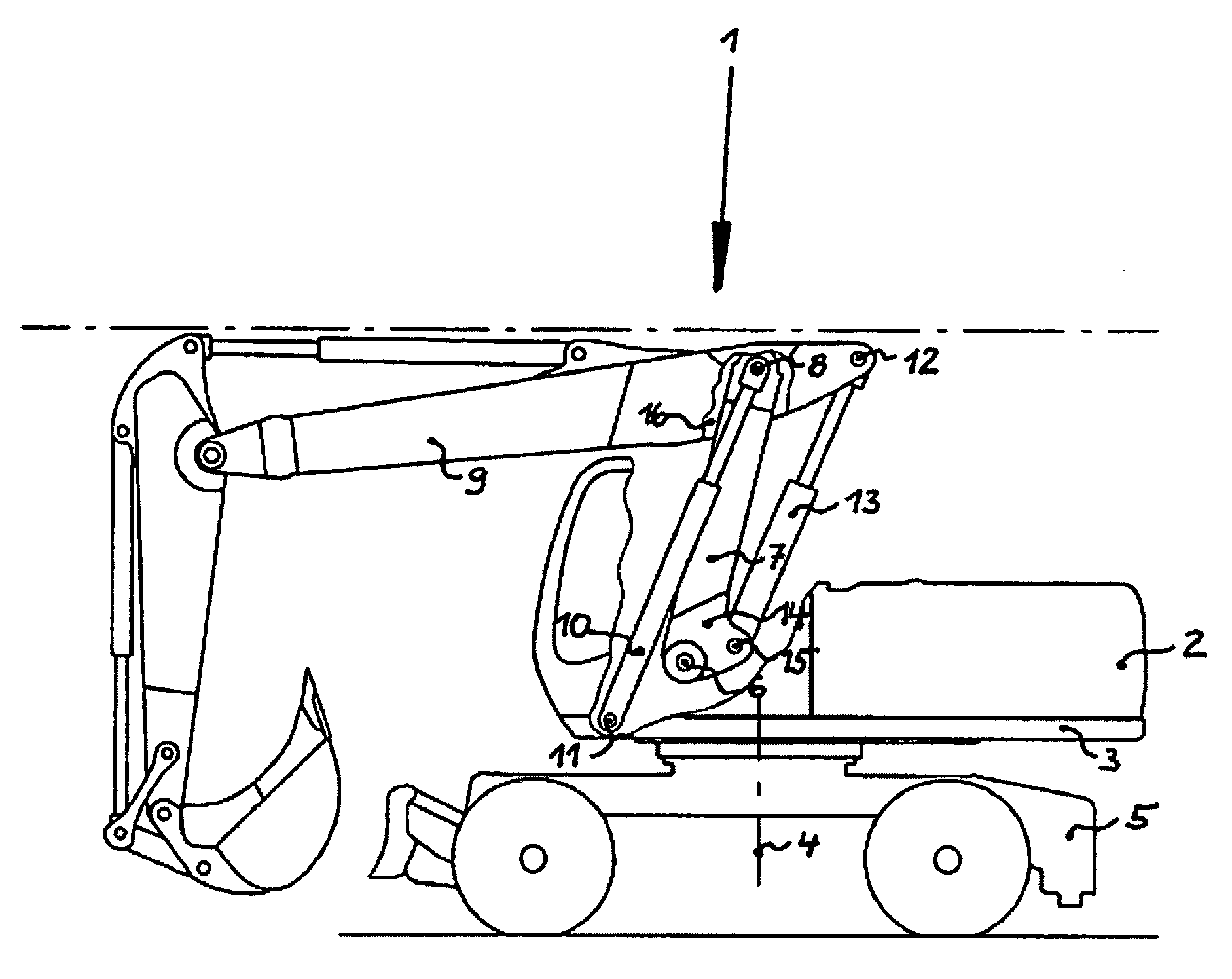
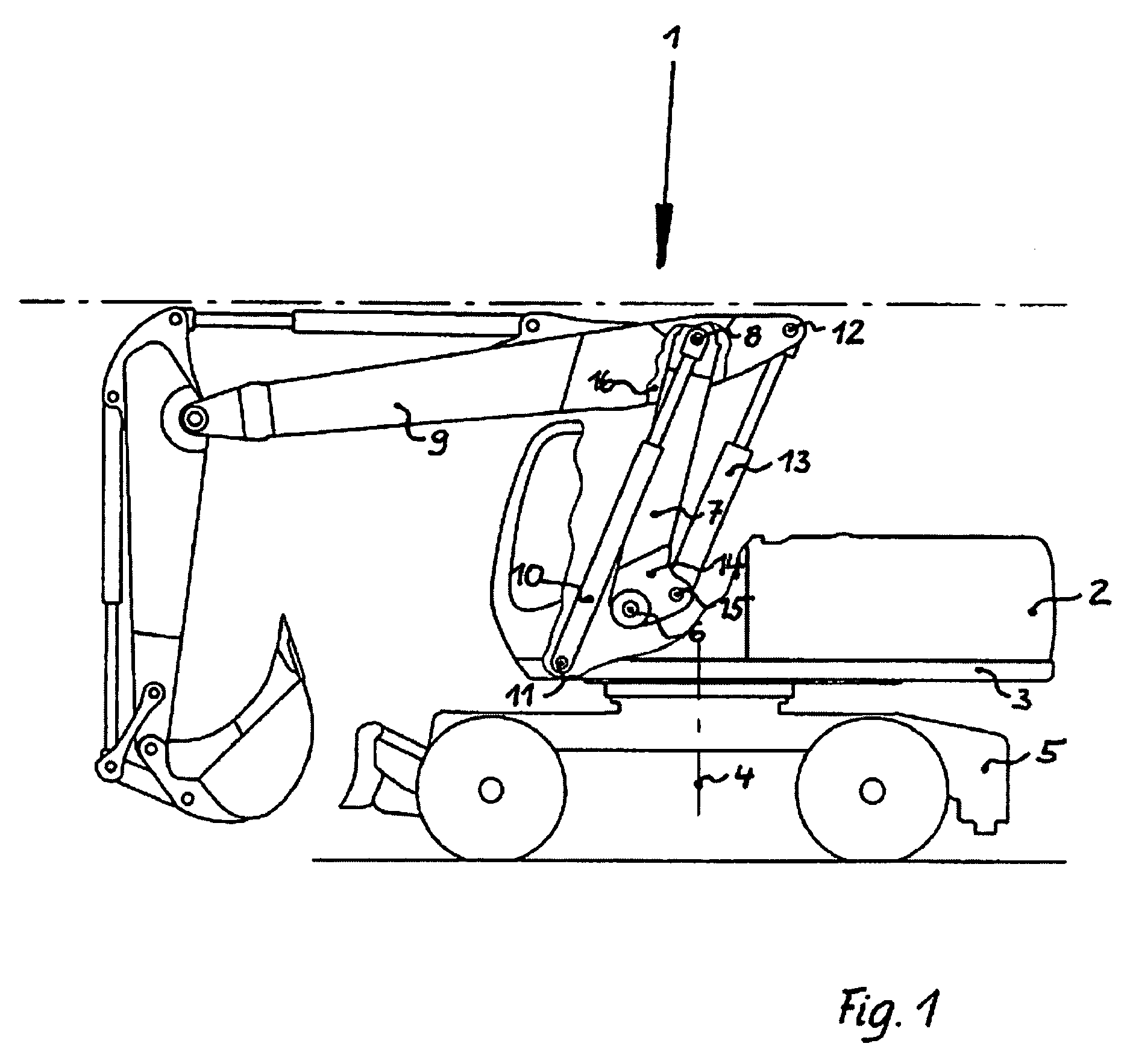
[0017]The side elevation in FIG. 1 shows the structure of the multiple boom 1 which is mounted on the revolving superstructure 2 and attached to frame 3 of the body of a self propelled excavator. The revolving superstructure 2 can be swiveled in a horizontal plane about a vertically aligned axis 4 in relation to the chassis 5. It consists firstly of a back boom 7, designated the first component, the lower end of which is mounted in a drag link 6 on the frame 3. Its upper end is connected to the mid boom 9, designated the second component, by a bearing 8, said bearing 8 being located inside the mid boom 9, immediately below its upper edge, at a certain distance from its rear end. Two hydraulic boom cylinders 10 are provided as third components for executing the swivel movement of the back boom 7. At one end they act upon the bearing 8 and are mounted at the other end on a knuckle 11, which is located on the frame 3 at a certain distance in front of the drag link 6 of the back boom 7....


PUM


Abstract

A bearing for use between components of a construction machine, particularly on a boom on excavators, loaders, cranes, and related equipment having a first component articulated to a second component by the bearing and in which a third component acts on the bearing. The bearing assembly having a pin extending in the direction of a swiveling axis of the bearing, borne in a bearing tube.

Description

FIELD OF THE INVENTION[0001]The invention concerns a bearing between components of a construction machine, particularly on the boom of excavators, loaders, cranes, etc. whereby two or more components are articulated at a bearing point.BACKGROUND OF THE INVENTION[0002]A very frequently encountered embodiment of such a bearing is found between the back and mid constituents of the boom of self-propelled excavators, on which one boom cylinder acts on each side, as a third component. In this case the lower end of the back boom is mounted in a drag link on the frame of the revolving superstructure. The upper end of the upward-pointing back boom takes the form of an upward-opening fork, in which the rear area of the mid boom is accepted in said bearing, at a certain distance in front of the rear end of the mid boom, seen in the direction of movement of the self-propelled excavator, both parts being connected to each other by means of a pin.[0003]To facilitate the swivel movement of the bac...

Claims


Application Information

Patent Timeline
IPC IPC(8): B66C23/00F16C33/22E02F3/96E02F9/00
CPCE02F9/006F16C11/02F16C11/045F16C2350/26
Inventor SCHMELING, RALFWILLAREDT, BERNHARDOERTEL, HOLGERDITZ, BIRGIT
Owner CNH BAUMASCHEN
Why Eureka
Try Eureka