Bolt element and a method for the attachment of a bolt element to a component of a composite material

a technology of composite materials and bolt elements, which is applied in the direction of bolts, nuts, screws, etc., can solve the problems of local weakening of components and further costs, and achieve the effects of simple realization, reduced labor intensity and convenient reception process

Active Publication Date: 2013-07-25
PROFIL VERBINDUNGSTECHN
View PDF18 Cites 9 Cited by
  • Summary
  • Abstract
  • Description
  • Claims
  • Application Information

AI Technical Summary

Benefits of technology

[0013]In principle it is not out of the question that a pre-piercing could be effected. For example, such a pre-piercing could take place during a manufacture of the fiber reinforced components in a press or in a drilling process, for example when a type of pre-positioning or pre-centering of the fiber reinforced component relative to another component or vice versa is to be ensured by the pre-piercing.
[0014]The bolt element can have an axial ring groove radially within the ring-like contact surface which is arranged concentric to the shaft part, and which is optionally equipped with features providing security against rotation. Furthermore the component can have a ring-like raised portion at its side remote from the head part. In accordance with an embodiment of the invention the bolt element is rotated until the raised portion enters into engagement with the axial ring groove and optionally with the features providing security against rotation provided there. The axial ring groove extends preferably from a radially inner end of the contact surface or from a radial outer edge of the head part up to the shaft part. Raised portions which arise through the pressing of the tip through the component or raised portions which are intentionally provided at the component can be received in ring groove. In order to facilitate the reception process the ring groove can have a rounded cross-sectional shape. Radially extending ribs or grooves can in particular be considered as features providing security against rotation and are preferably uniformly arranged around the periphery of the shaft part. The features providing security against rotation bring about a fixed clawing of the head part of the bolt element into the components so that an undesired release of the screw connection formed by the engagement of the thread cylinder and the internal thread is prevented. Furthermore, the radially inner side of the ring groove can have a diameter which is smaller than the outer diameter of the thread cylinder, with the material of the components around the hole, in particular in the region of the raised portion being so deformed that it at least substantially fills out the ring groove or enters into an undercut formed between the thread cylinder and the head part. As a result of such an engagement of the he...

Problems solved by technology

Both threaded inserts or eyes can already be integrated into the plastic component during the manufacture of the component, which is however very time consuming and complicated and leads to further costs and sometimes makes a local thicken...

Method used


Image

  • Bolt element and a method for the attachment of a bolt element to a component of a composite material
  • Bolt element and a method for the attachment of a bolt element to a component of a composite material
  • Bolt element and a method for the attachment of a bolt element to a component of a composite material

Examples


Embodiment Construction

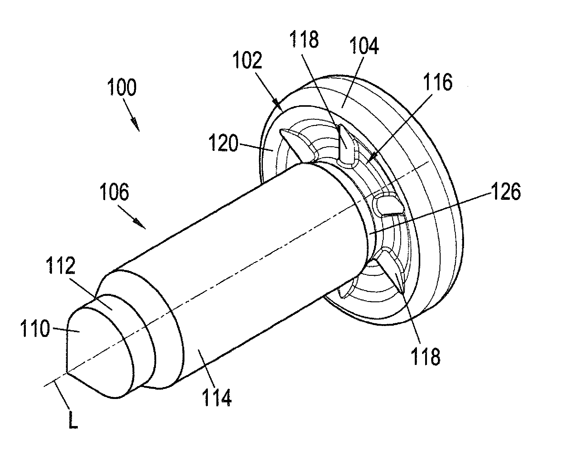
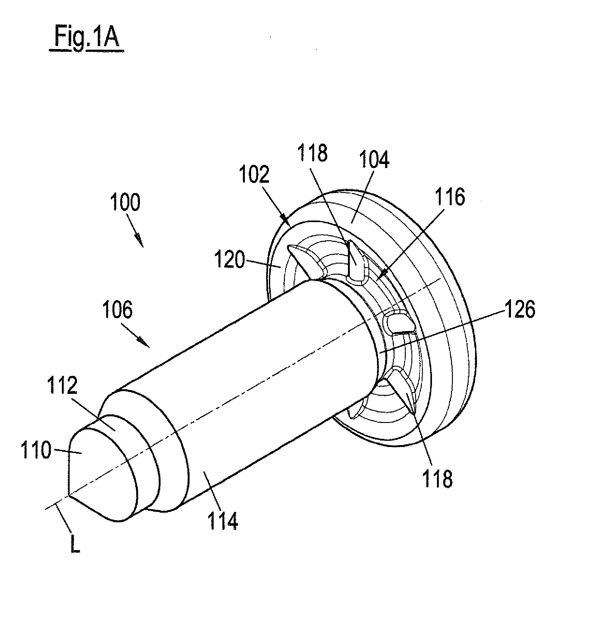
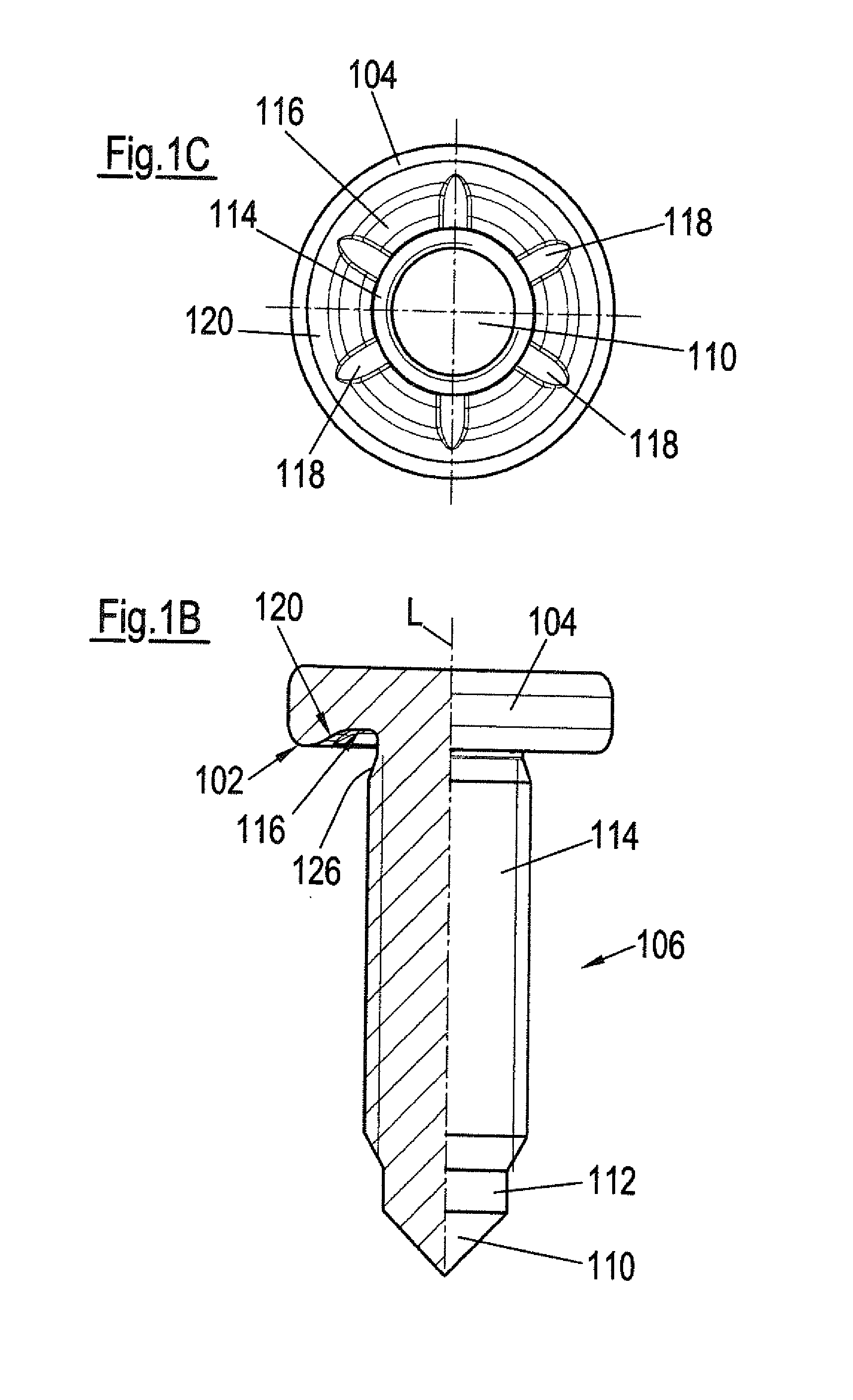
[0039]The bolt element 100 shown in FIGS. 1A-C has a head part 102 having an annular contact surface 102 and a shaft part 106 extending away from the head part 104. The shaft part 106 is provided at its end remote from the head part 104 with a tip 110 which merges via a cylindrical region 112 into a thread cylinder 114. The tip converges to a point.

[0040]An axial ring groove 116 is located radially inside the contact surface 102 with respect to a central longitudinal axis L of the bolt element 100. This ring groove 116 is arranged concentrically to the shaft part 106 and has features 118 providing security against rotation in the form of ribs which are formed in the radial direction at the base of the ring groove 116. The radially inner side of the ring groove 116 has a diameter which is smaller than the outer diameter of the thread cylinder 114. Furthermore, the thread cylinder 114 has thread run-out 120 which runs out adjacent to the head part 104 at the level of the contact surfa...


PUM

PropertyMeasurementUnit
Temperatureaaaaaaaaaa

Abstract

A method for the attachment of a bolt element to a component is described. The bolt element has a head part having a contact surface and a shaft part extending away from the head part, the shaft part having a tip provided at its end remote from the head part, the tip merging into a thread cylinder, optionally via a cylindrical region. The bolt element is pressed with the tip to the fore against the component and the tip is pressed through the component until the side of the component adjacent the head part of the bolt element enters to contact the thread cylinder and the tip thereby generates a hole in the component. The bolt element is subsequently turned so that the thread of the thread cylinder forms an internal thread in the wall of the hole. A bolt element is also claimed.

Description

CROSS-REFERENCE TO RELATED APPLICATIONS[0001]The present application claims priority under 35 U.S.C. §119 to German Patent Application No. 10 2012 001 086.9, filed on Jan. 20, 2012, the disclosure of which is expressly incorporated by reference herein in its entirety.FIELD OF THE INVENTION[0002]The present invention relates to a method for attaching a bolt element to a component consisting of a composite material such as a fiber reinforced plastic part or a fabric reinforced plastic part, with the bolt element having a head part and a shaft part extending away from the head part, with the shaft part being provided with a tip at its end remote from the head part and optionally merging via a cylindrical region into a thread cylinder.BACKGROUND OF THE INVENTION[0003]Composite materials are frequently used in most diverse areas and consist mainly of plastic with embedded fiber reinforcement The fiber reinforcement can for example take the form of tapes, fabrics, felts and mats. For exam...

Claims


Application Information

Patent Timeline
IPC IPC(8): F16B39/282B23P19/00
CPCB23P19/00F16B39/282Y10T29/49881F16B37/068F16B19/14F16B25/106B23P19/001B23P19/06B23P19/064F16B35/06
Inventor DIEHL, OLIVERHUMPERT, RICHARDLEMBACH, ANDREASSOWA, CHRISTIAN
Owner PROFIL VERBINDUNGSTECHN
Why Eureka
Try Eureka