Locking mechanism for a housing to hold a plug-in module

a technology of locking mechanism and plug-in module, which is applied in the direction of electrical apparatus, electrical apparatus, and electrical apparatus contruction details, etc., can solve the problems of time-consuming and laborious replacement of individual or multiple plug-in modules, complicated disassembly, and limited space for using tools to remove plug-in modules, etc., to achieve the effect of simple assembly and removal of plug-in modules

Inactive Publication Date: 2013-06-25
PHOENIX CONTACT GMBH & CO KG
View PDF6 Cites 0 Cited by
  • Summary
  • Abstract
  • Description
  • Claims
  • Application Information

AI Technical Summary

Benefits of technology

[0010]Given the indicated state of the art, the problem of the present invention therefore is to provide a locking system for a housing to hold at least one plug-in module as well as a housing equipped with a corresponding locking mechanism, where the locking mechanism or the housing allow the locking, while, on the other hand, a simple assembly and removal of the plug-in module can occur.

Problems solved by technology

Therefore, the replacement of individual or multiple plug-in modules is time consuming and laborious.
To reduce the construction space required for such an array, the individual housings sit very close to each other, so that the space available for using tools to remove plug-in modules is rather limited.
This disadvantage here is particularly the more complicated disassembly, and also that the user needs to use both hands, one to hold the plug-in module firmly, and the other to turn the screwdriver.
However, the disadvantage of this known state of the art is that when replacing a plug-in module, the removal requires, on the one hand, unlocking several connection elements, and, on the other hand, pulling off the unlocked plug-in module against strong retention forces.
However, the disadvantage of this state of the art is that there is no locking function, so that the loading is unilateral when the plug-in module is pushed out, with the result that the plug-in module is not pushed out along a straight line.
This solution as well requires the successive actuation of several mechanisms, to remove a plug-in module, so that the effort required for the disassembly is greater, while at the same time it is not possible to ensure the locking.
The disadvantage of this technical solution is the high cost of the different mechanisms, while, at the same time, no locking occurs.

Method used


Image

  • Locking mechanism for a housing to hold a plug-in module
  • Locking mechanism for a housing to hold a plug-in module
  • Locking mechanism for a housing to hold a plug-in module

Examples


Embodiment Construction

[0021]This application claims priority to German Application 10 2007 041 406.6 filed Aug. 31, 2007, the entire disclosure of which is incorporated by reference.

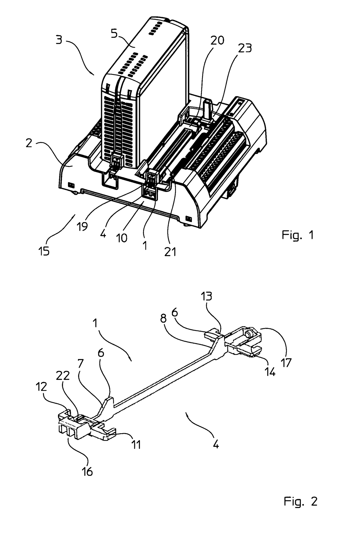
[0022]The locking mechanism according to the invention for a housing to hold at least one plug-in module presents an actuating mechanism to unlock the plug-in module. Here, the actuating mechanism is connected to a lifting mechanism whose function is to lift the plug-in module held in the housing when unlocking.

[0023]The locking mechanism according to the invention has many advantages. Because the actuating mechanism is connected to the lifting mechanism, the unlocking process lifts any plug-in module that may be held in the associated housing, so that the module can be removed more easily from the housing. Thus, the invention provides not only a locking and unlocking mechanism, the particularly electric or electronic plug-in module is also lifted simultaneously when unlocking to facilitate the removal. This is preferably als...


PUM


Abstract

Locking mechanism (1) and a housing (2) equipped with one such locking mechanism, to hold a plug-in module (5), and a modular system (3) which comprises a housing and a plug-in module, wherein the locking mechanism (1) has an actuating mechanism (4) for unlocking of the plug-in module. The invention is characterized in that the actuating mechanism (4) is connected to a lifting mechanism (6) in order to lift a plug-in module (5) held in the housing (2) when unlocking.

Description

REFERENCE TO RELATED APPLICATION[0001]This application claims priority to German Application 10 2007 041 406.6 filed Aug. 31, 2007.FIELD OF THE INVENTION[0002]The present invention relates to a locking mechanism and a housing to hold at least one plug-in module, which housing is equipped with such a locking mechanism, and where an actuating mechanism is provided for unlocking the plug-in module.BACKGROUND[0003]Housings according to the invention preferably hold modular input-output modules, i.e., electric or electronic modules, which are used in control installations or in process automation. The housings here are typically placed on, for example, a mounting and / or carrier rail, and connected with a bus system or a bridge system. One or more plug-in modules are inserted in the housing, so that, when replacing a plug-in module, the appropriate module is pulled out, and a new or appropriate different module can be plugged in. To pull off an inserted module, strong retention forces mus...

Claims


Application Information

Patent Timeline
Patent Type & Authority Patents(United States)
IPC IPC(8): H05K7/00
CPCH05K5/0204H05K7/1474
Inventor SOFKER, JORGBEST, FRANK
Owner PHOENIX CONTACT GMBH & CO KG
Why Eureka
Try Eureka