Control Arrangement

a technology of control arrangement and control arrangement, applied in the direction of baling, agriculture tools and machines, agriculture, etc., can solve problems such as inability, and achieve the effect of supporting safely

Active Publication Date: 2007-09-13
DEERE & CO
View PDF2 Cites 21 Cited by
  • Summary
  • Abstract
  • Description
  • Claims
  • Application Information

AI Technical Summary

Benefits of technology

[0010]If the carrier is configured with a concave surface, the cylindrical bale is supported safely. The depth of the trough is a function of the inclination of the slopes to be expected, the size of the bale, the speed and the method of handling it.
[0011]While the bale could fundamentally fail out of the baler that forms the vehicle and fall directly onto the ground, such a resulting force, that is particularly detrimental on a slope, is avoided in that the bale is caught and deposited on the ground in a controlled manner. Since this movement is normally executed as a pivoting movement instead of a parallelogram movement, that axis is provided with an inclination to the ground, it is located between a horizontal pivoting arm and a vertical pivoting arm in a raised position of the vertical pivoting arm, the inclination extends approximately vertically in a condition close to the ground. The vertical pivot arm itself is a moved about an axis preferably extending transverse to the direction of operation and normally in the plane of the inclination of the slope. However, the horizontal pivot arm could be rotated or pivoted about an axis extending in the direction of operation, so that the bale can be deposited on its end face.

Problems solved by technology

In contrast to the state of the art, a bale weighing up to a ton need not be turned on the ground, which is possible only with difficult anyway with a relatively light baler.
It is also not possible that the bale rolls down a slope into the back side of the baler, before its position is corrected.

Method used


Image

  • Control Arrangement
  • Control Arrangement
  • Control Arrangement

Examples


Embodiment Construction

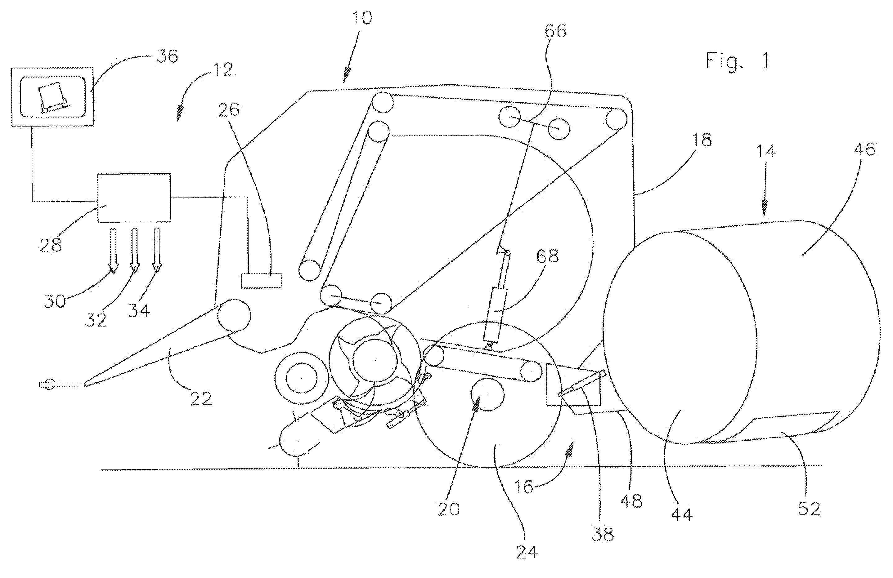
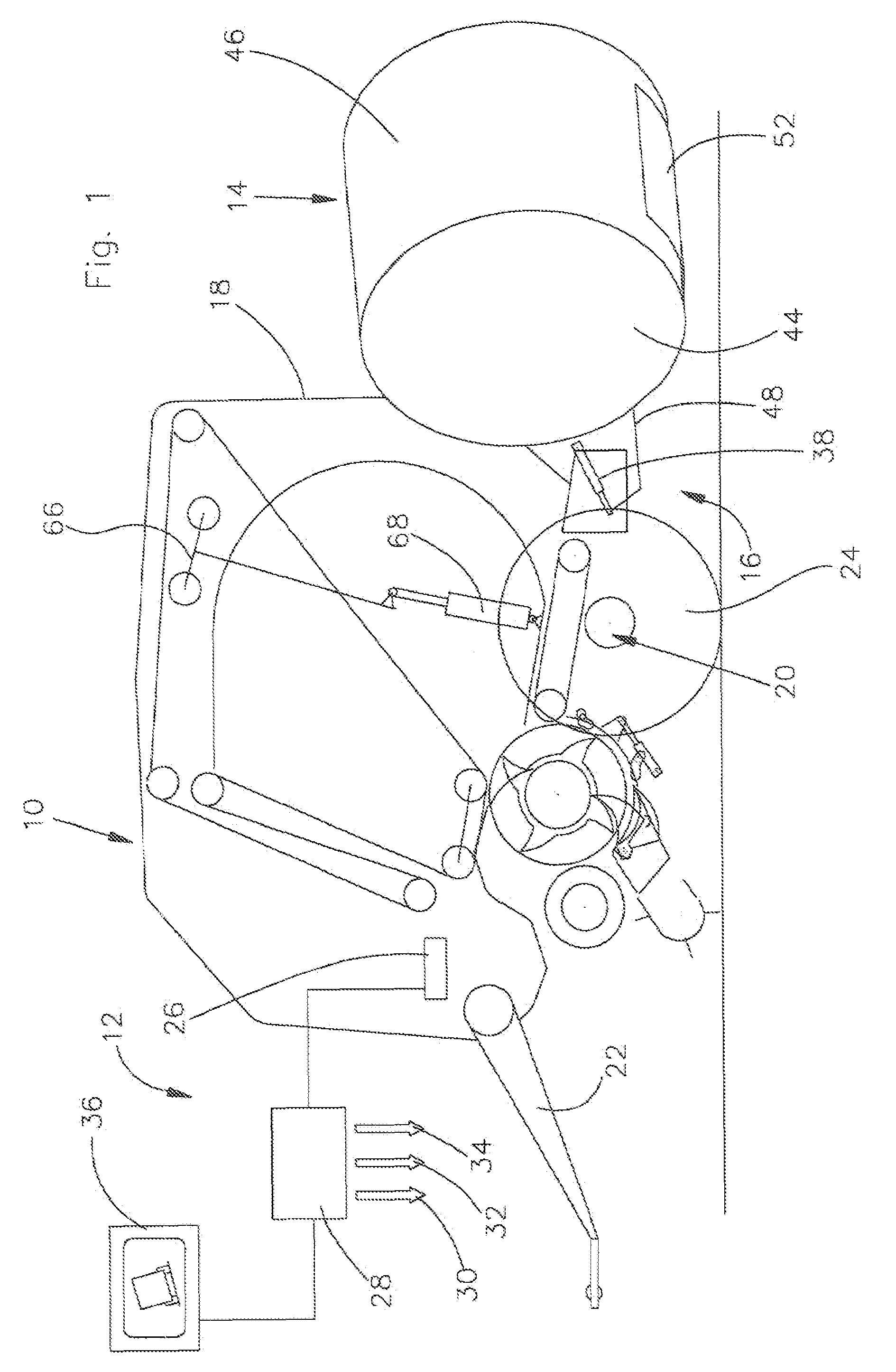
[0023]A vehicle 10, shown in FIG. 1, is shown there as a rotobaler that can be attached to a towing vehicle, not shown, it is provided with a control arrangement 12 and forms a cylindrical bale 14 that can be deposited on the ground by means of a discharge arrangement 16.

[0024]Aside from a multitude of components of no significance to the invention, the vehicle 10 is provided with a frame 18, a chassis 20, a towbar 22 and the outlet arrangement 66.

[0025]The frame 18 rests on the chassis 20, carries the towbar 22 at its front and the discharge arrangement 16 towards the rear.

[0026]The chassis 20 is supported on wheels 24 on the ground and follows an inclination extending transverse to the direction of operation and thereby the stands more or less steeply on the slope. The wheels 24 or the chassis 20 as a whole could be attached relative to the frame 18 so that it can be steered.

[0027]The outlet arrangement 66 is configured as a so-called gate, outlet flap or the like and can be broug...


PUM


Abstract

A rotobaler is provided with an inclination sensor that recognizes an inclination to the side as well as in the longitudinal direction. This inclination sensor generates a signal coupled to a computer that, in turn, controls a display arrangement in order to indicate whether a base that is to be unloaded from the rotobaler can be safely unloaded considering the existing inclination of the rotobaler. In the event an unsafe inclination is present, either the computer sends out a control signal which blocks an operation for depositing the bale on the ground, or causes the bale to be oriented in such a way during the discharge process that the longitudinal centerline of the bale is parallel to the inclination of the slope.

Description

FIELD OF THE INVENTION[0001]The invention concerns a control arrangement of a vehicle that deposits cylindrical bales on the ground, with an inclination sensor, that generates a signal from the inclination of the vehicle, as well as a rotobaler or a bale wrapping arrangement.BACKGROUND OF THE INVENTION[0002]DE 199 10 555A1 discloses a rotobaler with a discharge arrangement configured as a scale for a cylindrical bale. An inclination sensor is associated with this discharge arrangement, it corrects the results of the weighing that may have been in error due to the inclination.[0003]EP 1 512 320 A2 reveals a rotobaler that deposits a cylindrical bale on the ground, where the exit of the cylindrical bale is limited by a double-wing door and its position is corrected, if necessary so that it cannot roll down any slope.[0004]The problem underlying the invention is seen in the fact that the deposit of a cylindrical bale on a slope is, as ever, a serious matter, and that problems can be av...

Claims


Application Information

Patent Timeline
Patent Type & Authority Applications(United States)
IPC IPC(8): B30B5/06
CPCA01F15/08A01F2015/0891A01F2015/0808A01F15/0883
Inventor VIAUD, JEAN
Owner DEERE & CO
Why Eureka
Try Eureka