
Ice buggy

a technology for ice buggy and ice axe, which is applied in the direction of vehicle components, other angling devices, lighting and heating apparatus, etc., can solve the problems of complicated means for connecting augers, difficult to connect augers, and tiring tasks

Inactive Publication Date: 2007-09-13
GANCARZ ROBERT M +1
View PDF21 Cites 4 Cited by
  • Summary
  • Abstract
  • Description
  • Claims
  • Application Information

AI Technical Summary

Benefits of technology

[0008]It is a primary object of the invention to provide a small, inexpensive, lightweight, wheeled vehicle in the nature of a buggy for movement over frozen bodies of water such as ponds and lakes, with the vehicle being powered by a gasoline engine which is also used to power an ice auger.
[0010]With the invention hereof, the gasoline engine is separated from the ice auger and detachably connected to the drive shaft of the buggy for powering the vehicle, thus providing the ice fisherman with very desirable mobility on large ponds and lakes.
[0011]It is a further object of the invention to provide an ice buggy which is very affordable since it can be sold without a gasoline engine, in view of the fact that most modern ice fishermen already own a power auger.
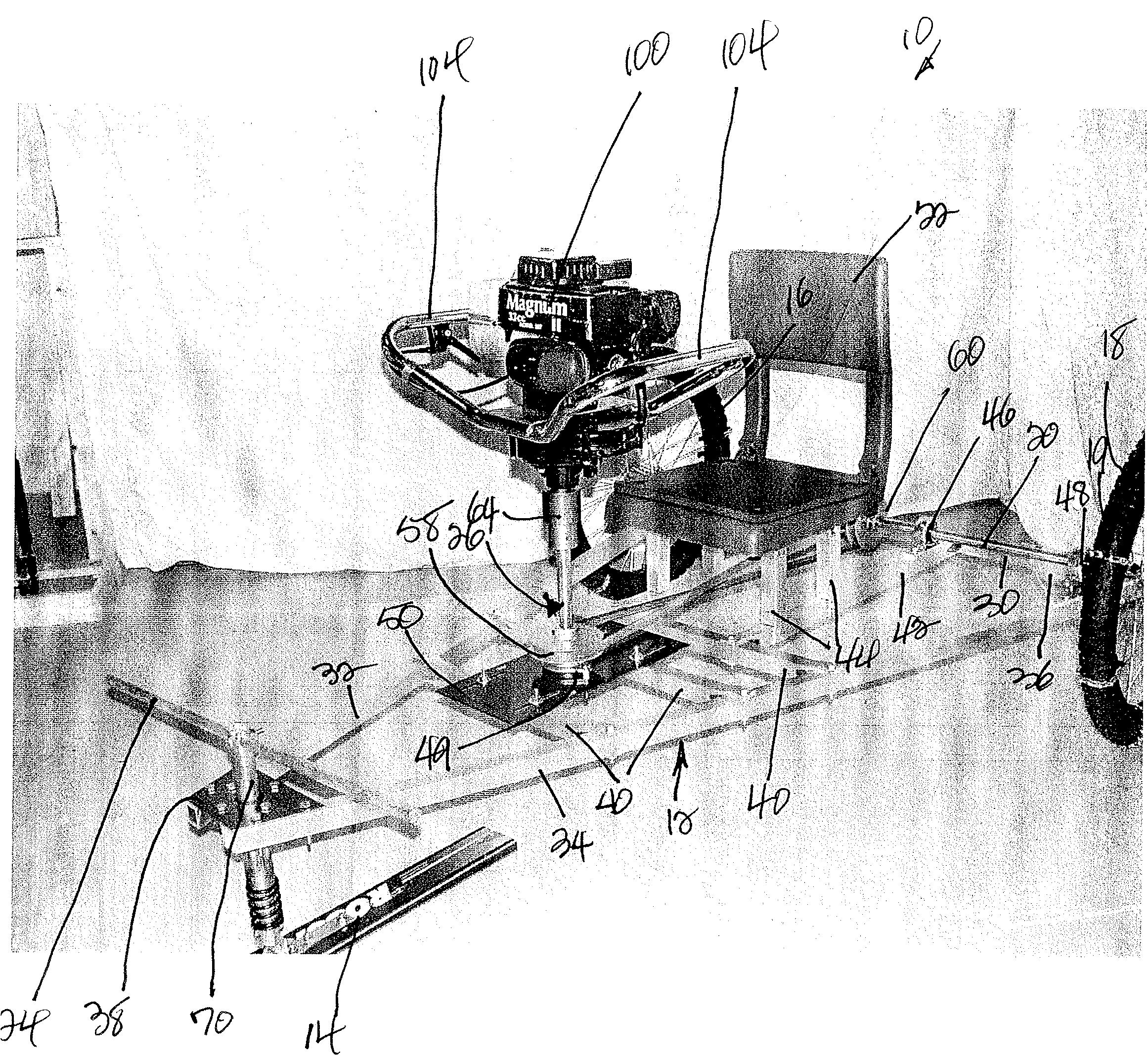
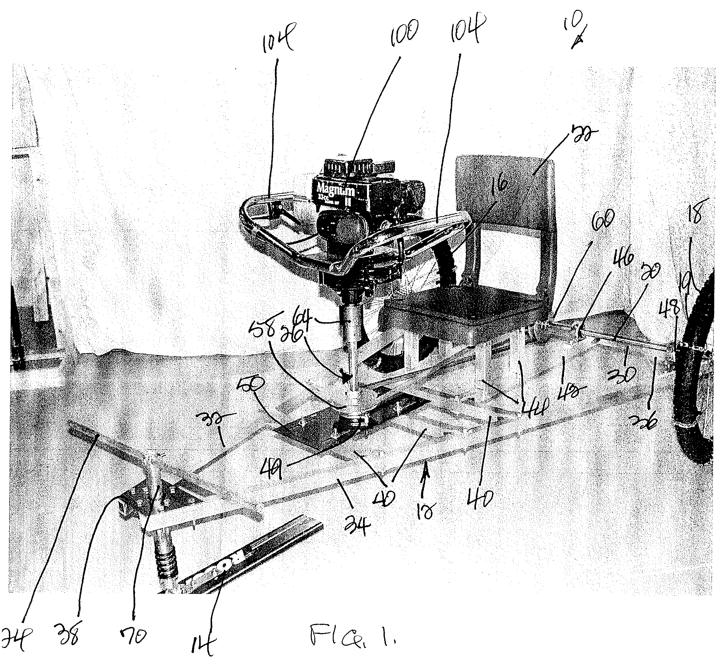
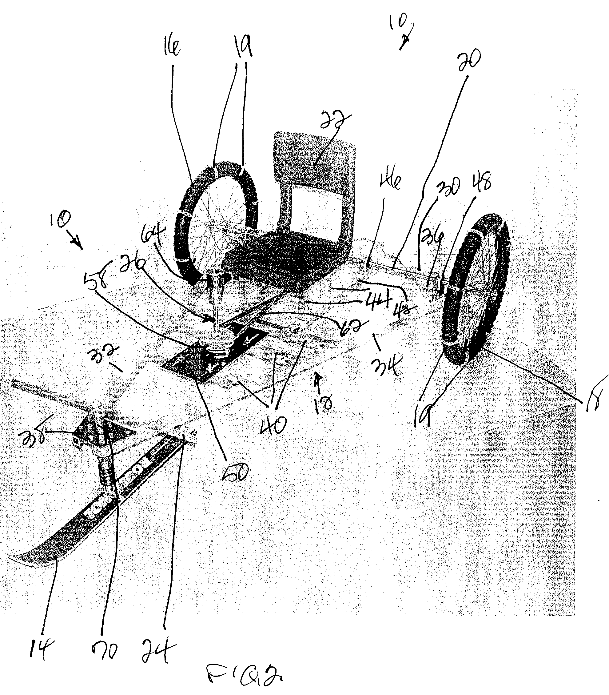
[0013]The wheels of the ice buggy are preferably of large diameter, such as 20 inch bicycle wheels, in order to provide ample clearance between the buggy frame and the ice.

Problems solved by technology

In the past, holes have been formed in the ice for ice fishing by the use of ice chisels or hand augers, a task which was tiring and tedious, especially with ice sometimes as thick as 1 to 2 feet.
However, vehicles such as tractors and snowmobiles are expensive and are not readily available to the average ice fisherman.
In addition, the means for connecting augers thereto is complicated and requires special tools and equipment.

Method used


Image

  • Ice buggy
  • Ice buggy
  • Ice buggy

Examples


Embodiment Construction

[0033]Referring first to FIGS. 1-9, an ice buggy embodying a first form of the invention is generally indicated by 10 and includes a frame 12 which supports the following: ski means 14; spaced rear wheels 16 and 18 mounted on an axle 20; a seat 22; a steering T-bar 24; an ice buggy drive shaft generally indicated by 26 which is powered by a gasoline engine 100; and belt and pulley drive means generally indicated by 28 for operatively connecting drive shaft 26 to axle 20.

[0034]Gasoline engine 100 is otherwise and alternatively part of a power auger, generally indicated by 101, of the type shown in FIG. 3, used to drive an ice auger 102 and is provided with handles 104 for grasping the unit during use.

[0035]As best seen in FIG. 4, gasoline engine 100 and ice auger 102 are detachably interconnected by a stud or bolt 106 which extends through provided openings in a motor shaft 108 of gasoline engine 100 and through a main shaft 110 of ice auger 102.

[0036]Frame 12 of ice buggy 10 is pref...


PUM


Abstract

A small, inexpensive, lightweight vehicle in the nature of a wheeled buggy is provided for movement over frozen bodies of water such as ponds and lakes, with the vehicle being powered by a gasoline engine which is alternatively used to power an ice auger.

Description

CROSS REFERENCE TO RELATED APPLICATIONS[0001]This application claims the benefit of U. S. Provisional Application Ser. No. 60 / 780,254, filed on Mar. 8, 2006, which is hereby incorporated by reference.FIELD OF THE INVENTION[0002]The invention relates to vehicles for movement over frozen bodies of water and to augers for use by ice fishermen for boring holes through the ice.BACKGROUND OF THE INVENTION[0003]In the past, holes have been formed in the ice for ice fishing by the use of ice chisels or hand augers, a task which was tiring and tedious, especially with ice sometimes as thick as 1 to 2 feet.[0004]More recently, in response to the fast growing popularity of ice fishing as a winter sport, a wide variety of power augers has become available for use by ice fishermen for drilling holes in the ice to set up fishing equipment such as ice tilts and the like.[0005]Snowmobiles are well known for use as a means for motorized transportation over snow and ice.[0006]It is also known to driv...

Claims


Application Information

Patent Timeline
Patent Type & Authority Applications(United States)
IPC IPC(8): F25C5/04
CPCB62M27/02A01K97/01
Inventor GANCARZ, ROBERT M.GANCARZ, DANIEL J.
Owner GANCARZ ROBERT M
Learn More