
Clamp for holding solar collectors on roofs

a solar collector and clamping technology, applied in the field of clamps, can solve the problems of unsatisfactory fastening, unsatisfactory fastening of the header, and inability to completely satisfy such roofs, and achieve the effect of eliminating abrasion of the roof covering

Active Publication Date: 2005-09-27
PLASTIC MAGEN A C S
View PDF20 Cites 12 Cited by
  • Summary
  • Abstract
  • Description
  • Claims
  • Application Information

AI Technical Summary

Benefits of technology

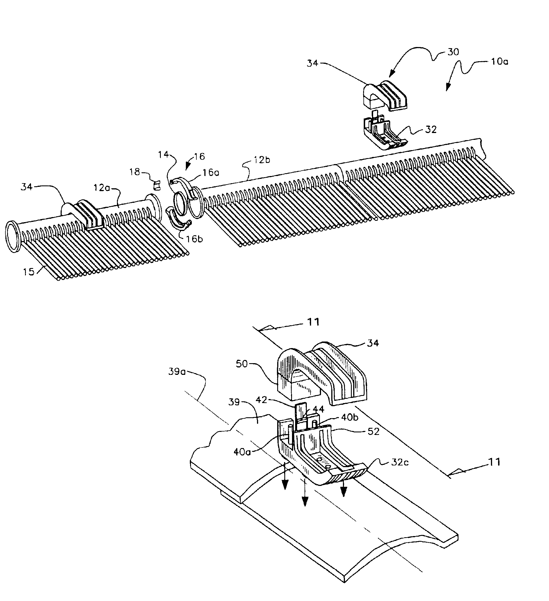
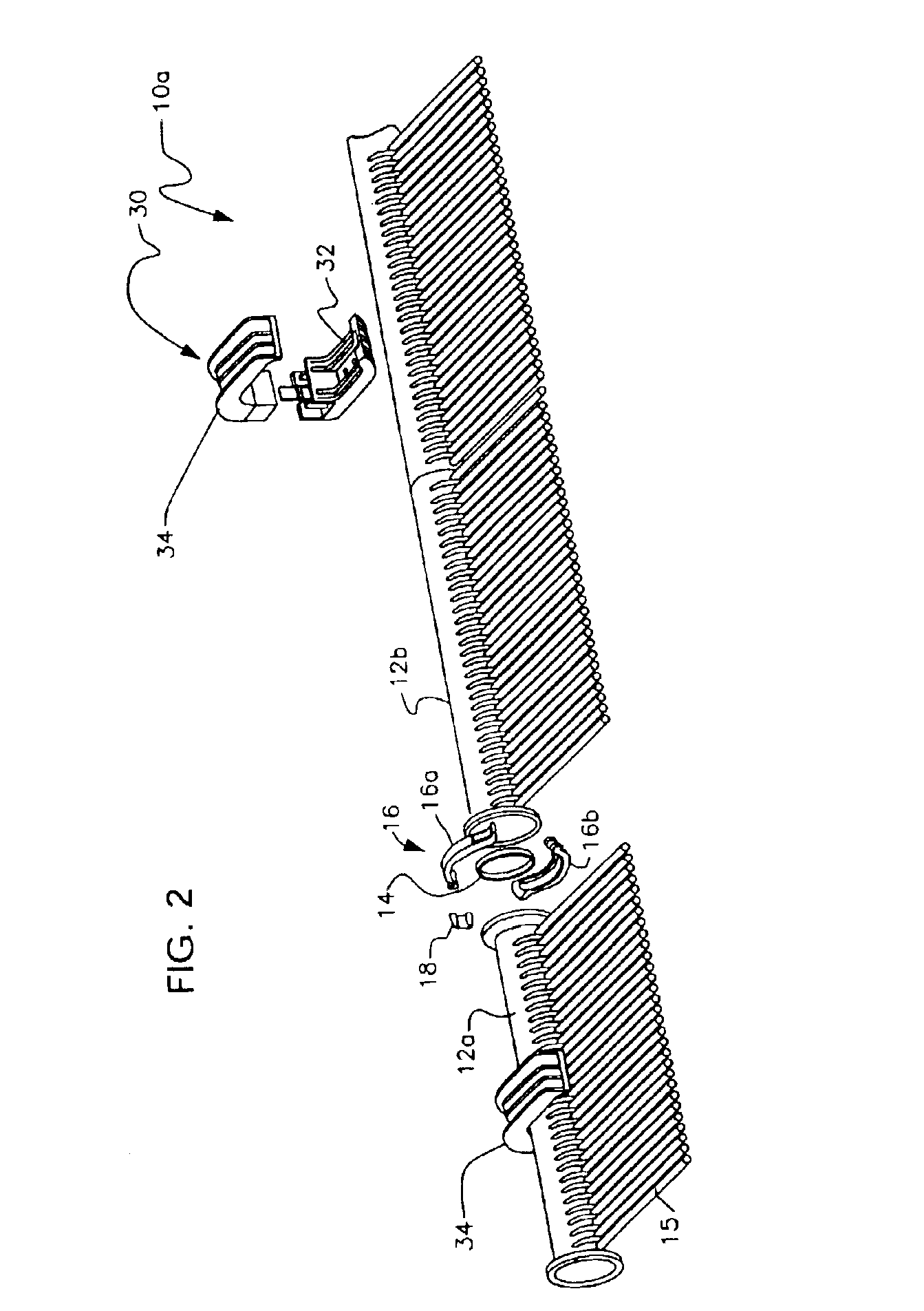
"The invention is a new and useful clamp for holding a solar collector header on a roof. The clamp is designed to hold the header in place without gripping it, so as to not damage the roof. It includes a base that overlies the roof covering and a clamp top that can be attached to the base. The space between the clamp base and the clamp top is large enough to allow for the expansion and contraction of the header without stressing the fasteners that secure the clamp to the roof. The clamp base has a plurality of feet that engage the roof covering and a base wall with a recess for inserting fastenings. The clamp top has a pedestal and a space for inserting a screw. The clamp is easy to install and provides flexibility in positioning the header."

Problems solved by technology

It is not completely satisfactory on such roofs, however, for several reasons.
If there is no rafter or other support beneath one or both of the apertures, the resulting fastening can be unsatisfactory.
If the apertures are not aligned with a rafter or other support element below the roof, the fastening of the header will be unsatisfactory for the reason stated above.
Since the position of the pipe-joining clamp determines the position of the Z-bar and hence of the fastening means, the person designing the solar collection installation is restricted and an optimal installation where all fastening members are secured in rafters or other support members often cannot be achieved.
Attaching such clamps to rafters or other optimal spots on the roof, therefore, is virtually impossible.
The current art is even less satisfactory on barrel tile roofs because each barrel tile presents a convexity.
The pre-drilled apertures of the Z-bar are unlikely to match the peaks of the tiles, with the result that one of the fastening means can be placed at the peak of a tile, but the adjacent fastening means is unlikely to match a peak.
The resulting clamping effect is less than optimal.
Other clamps and straps have the same detriment since they must attach to the roof exactly where spacing occurs between panels or sets of tubes.
Z-bars are also unsatisfactory because they space the header slightly above the roof, but not by much.
Similarly, the design of a Z-bar does not accommodate longitudinal expansion of a header.
When the header expands or contracts due to temperature fluctuations, the fastening screws are stressed and become loose and may even pop out under the force of the expansion or contraction.
This of course unacceptably leads to a roof with leaks.
Moreover, the collector itself may break under the strain.
This inadequate clearance between a header and roof provided by a Z-bar also leads to abrasion of the roof as the header expands and contracts.
Straps and other clamps do not lift the header off the roof at all and lead to severe abrasion of the roof and the header.
Z-bars are even less satisfactory on barrel tile roofs because each barrel tile presents a convexity.
The pre-drilled apertures of the Z-bar are unlikely to match the peaks of the tiles, with the result that one of fastening means can be placed at the peak of a tile, but the adjacent fastening means is unlikely to match a peak.
The resulting clamping effect is less than optimal.
Z-bars and other clamps are also unsatisfactory because they limit the header movement that results from heat driven expansion and contraction of the collector in the lateral and longitudinal directions.
When the header expands or contracts due to temperature fluctuations, the fastening screws are stressed and become loose and may even pop out under the force of the expansion or contraction.
This of course unacceptably leads to a roof with leaks.
Moreover, the collector itself may break under the strain.

Method used


Image

  • Clamp for holding solar collectors on roofs
  • Clamp for holding solar collectors on roofs
  • Clamp for holding solar collectors on roofs

Examples


Embodiment Construction

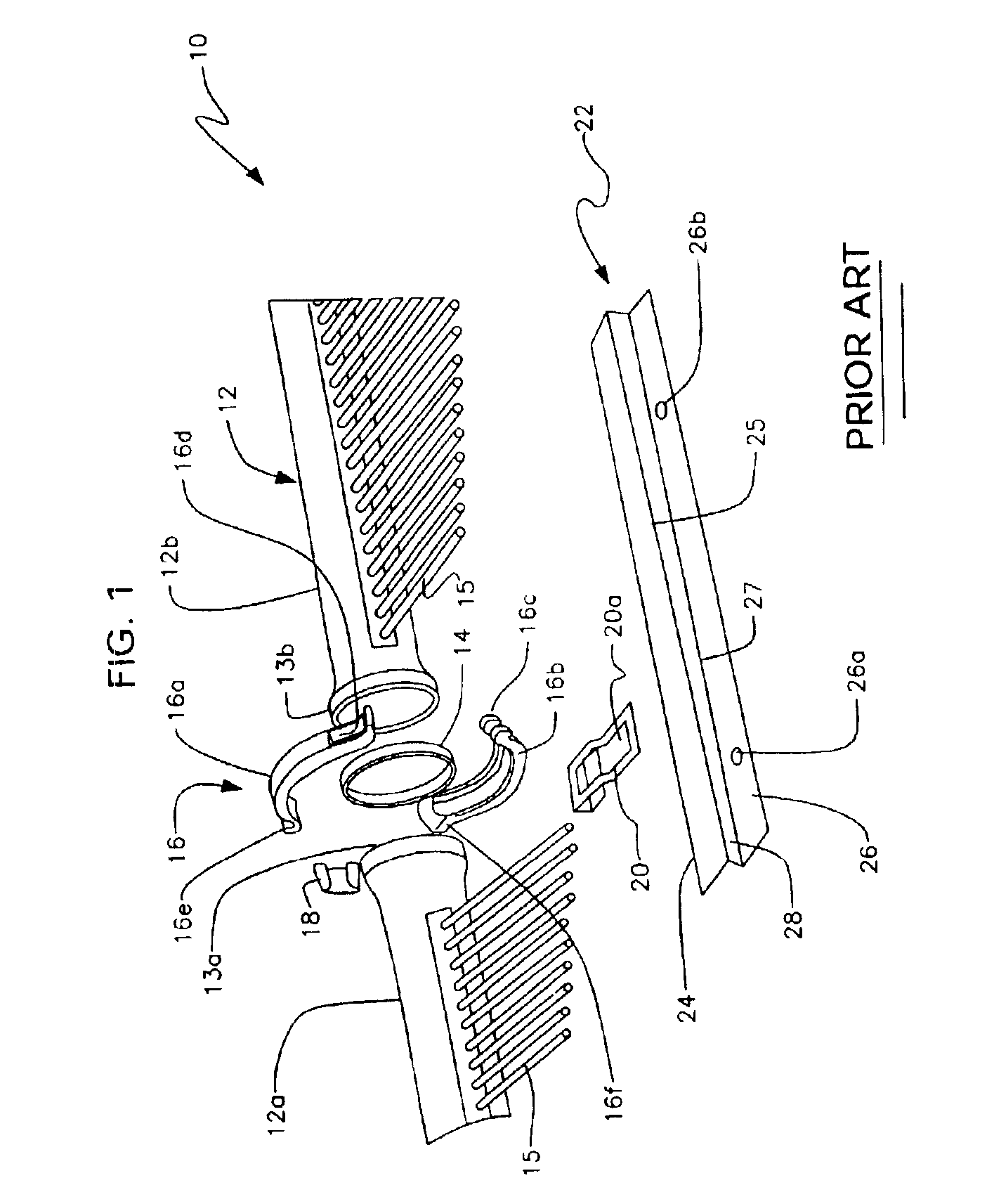
[0058]Referring to FIG. 1, it will there be seen that the reference numeral 10 denotes a prior art structure as a whole.

[0059]The top panel header is denoted 12 and typically is formed by pipes 12a and 12b that are interconnected to one another by a clamping assembly. Each pipe 12a, 12b has a slightly enlarged end 13a, 13b, respectively. A water-tight, resilient gasket 14 is positioned in sandwiched relation between said enlarged ends 13a, 13b and said enlarged ends are clamped to one another by a clamp 16 having a top 16a and a bottom 16b.

[0060]Although not depicted, a bottom header having essentially the same construction as top header 12 is interconnected to said top header 12 by a plurality of pipes, collectively denoted 15. Swimming pool water is delivered by thermo-siphoning or mechanical pump means to the unillustrated bottom header. The water is heated by the sun as it flows through pipes 15 en route to the top header and the heated water is then returned to the pool.

[0061]...


PUM


Abstract

A clamp having a clamp base that is attachable to a flat or sloped roof. A clamp top is releasably attachable to the clamp base. The clamp top includes a pedestal that is snap-fittingly engaged to the clamp base. The pedestal is made in two parts that are interconnected by an interconnecting wall that is releasably engaged by a locking member that forms a part of the clamp base. The header of a solar collector is confined in a space defined by the clamp base and clamp top. In a barrel tile application, a plurality of feet are attached to the bottom of the clamp base. At least one foot abuts the tile on opposite sides of a longitudinal axis of the tile. The bottom of each foot is contoured to match the convex surface of the tile. No feet are needed where the roof covering is flat.

Description

BACKGROUND OF INVENTION[0001]1. Field of the Invention[0002]This invention relates, generally, to clamps. More particularly, it relates to a clamp for holding solar collectors or similar items to a flat or sloped roof covered by shingles, tin, barrel tile, or other type of roof covering.[0003]2. Description of the Prior Art[0004]A roof-mounted solar collector often includes a pair of parallel main pipes, usually called the top header and the bottom header, that are interconnected by a plurality of smaller pipes disposed at right angles to the top and bottom headers. On a sloped roof, the top header is the header at the higher of the two elevations. Water from a swimming pool is pumped to the bottom header from which it flows into the smaller pipes where heat from the sun is absorbed before the water flows into the top header. The heated water flowing through the top header is returned to the pool.[0005]A clamp known as a Z-bar is currently in use as the means for mounting a header t...

Claims


Application Information

Patent Timeline
Patent Type & Authority Patents(United States)
IPC IPC(8): F24J2/52F24J2/00F24J2/04F24J2/46
CPCF24J2/045F24J2/4647F24J2/5245F24J2/5256F24J2002/4665Y10T403/608Y02E10/44Y02E10/47Y10T403/602Y10T403/606Y10T403/60Y02B10/20F24S25/61F24S80/30F24S20/67F24S2025/6004F24S25/634Y02A30/60
Inventor SHATZKY, JOSEF
Owner PLASTIC MAGEN A C S
Learn More