
Methods and apparatus for mounting an impeller with positional repeatability

a technology of position repeatability and mounting method, which is applied in the direction of non-positive displacement fluid engine, pump components, liquid fuel engine components, etc., can solve the problems of inability to accurately repeat the position of the assembled impeller, loss of original imbalance, and insurmountable difficulty, so as to prevent the loosening of the retaining nut

Inactive Publication Date: 2019-04-23
CONNECTING PRODS
View PDF31 Cites 4 Cited by
  • Summary
  • Abstract
  • Description
  • Claims
  • Application Information

AI Technical Summary

Benefits of technology

The patent text describes a new way of mounting and retaining impellers on motor shafts that improves repeatability and balance. This method involves using two flat surfaces on the motor shaft to prevent rotation of the impeller, which may help to prevent the retaining nut from coming loose when the impeller is stopped or accelerated. By aligning the impeller hub with the motor shaft and tightly clamping it in place with a retaining nut, the new method achieves a close to perfect balance and repeatability throughout the life of the device. The technical effects of this patent text are improved repeatability, vibration intact, and ease of assembly and disassembly.

Problems solved by technology

An insurmountable difficulty comes with this method.
This allowance makes accurate repeatability of the position of the assembled impeller impossible.
Even if the original assembly of the impeller to motor shaft is carefully balanced, the first time the impeller must be loosened for cleaning or other reasons, the original position is not repeatable and the original imbalance attainment is lost.
In addition, the removal of material when milling the flats renders the shaft weaker and liable to stress relieving creep, which can further disturb the centralization and straightness of the shaft.
The amount of eccentricity which is evident when a 170 gram impeller is confined to a 0.4 gram inch imbalance tolerance happens to be 0.0023″, so it can be seen that achieving and keeping the specified imbalance is impossible with the current art, which is in widespread use and therefore also makes unpleasant vibration impossible to remove.

Method used


Image

  • Methods and apparatus for mounting an impeller with positional repeatability
  • Methods and apparatus for mounting an impeller with positional repeatability
  • Methods and apparatus for mounting an impeller with positional repeatability

Examples


Embodiment Construction

[0039]The present invention now will be described more fully hereinafter with reference to the accompanying drawings, in which illustrative embodiments of the invention are shown. In the drawings, the relative sizes of regions or features may be exaggerated for clarity. This invention may, however, be embodied in many different forms and should not be construed as limited to the embodiments set forth herein; rather, these embodiments are provided so that this disclosure will be thorough and complete, and will fully convey the scope of the invention to those skilled in the art.

[0040]It will be understood that when an element is referred to as being “coupled” or “connected” to another element, it can be directly coupled or connected to the other element or intervening elements may also be present. In contrast, when an element is referred to as being “directly coupled” or “directly connected” to another element, there are no intervening elements present. Like numbers refer to like elem...


PUM


Abstract

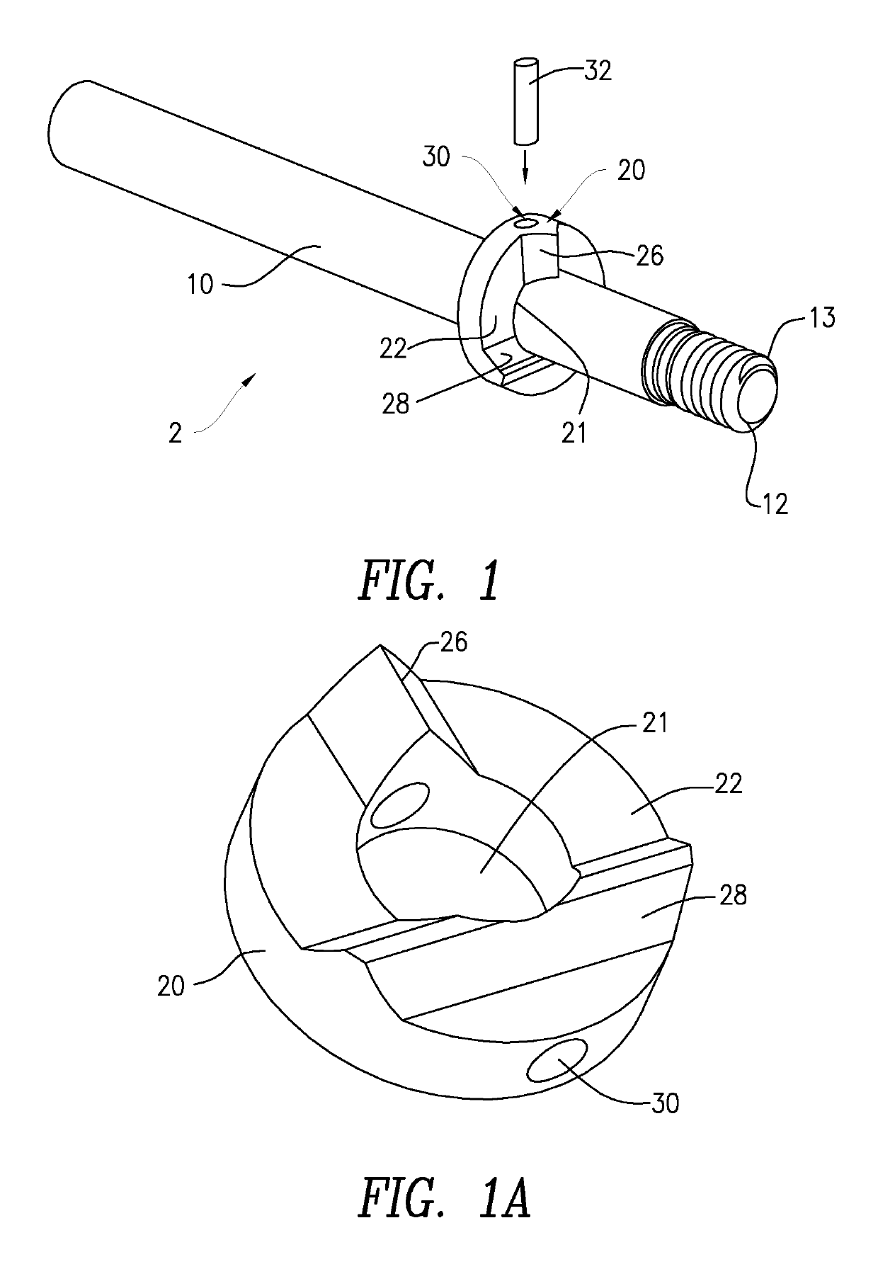
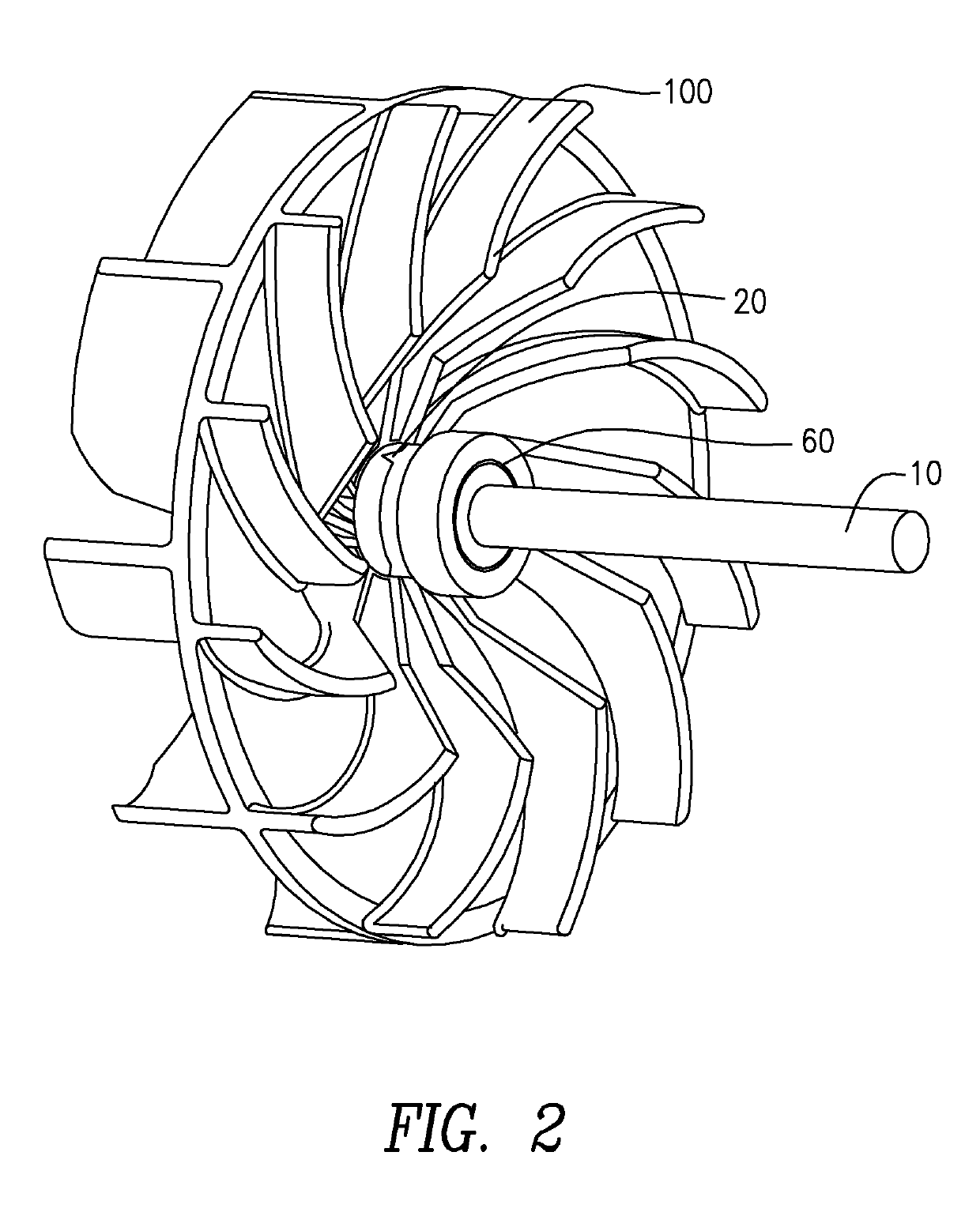
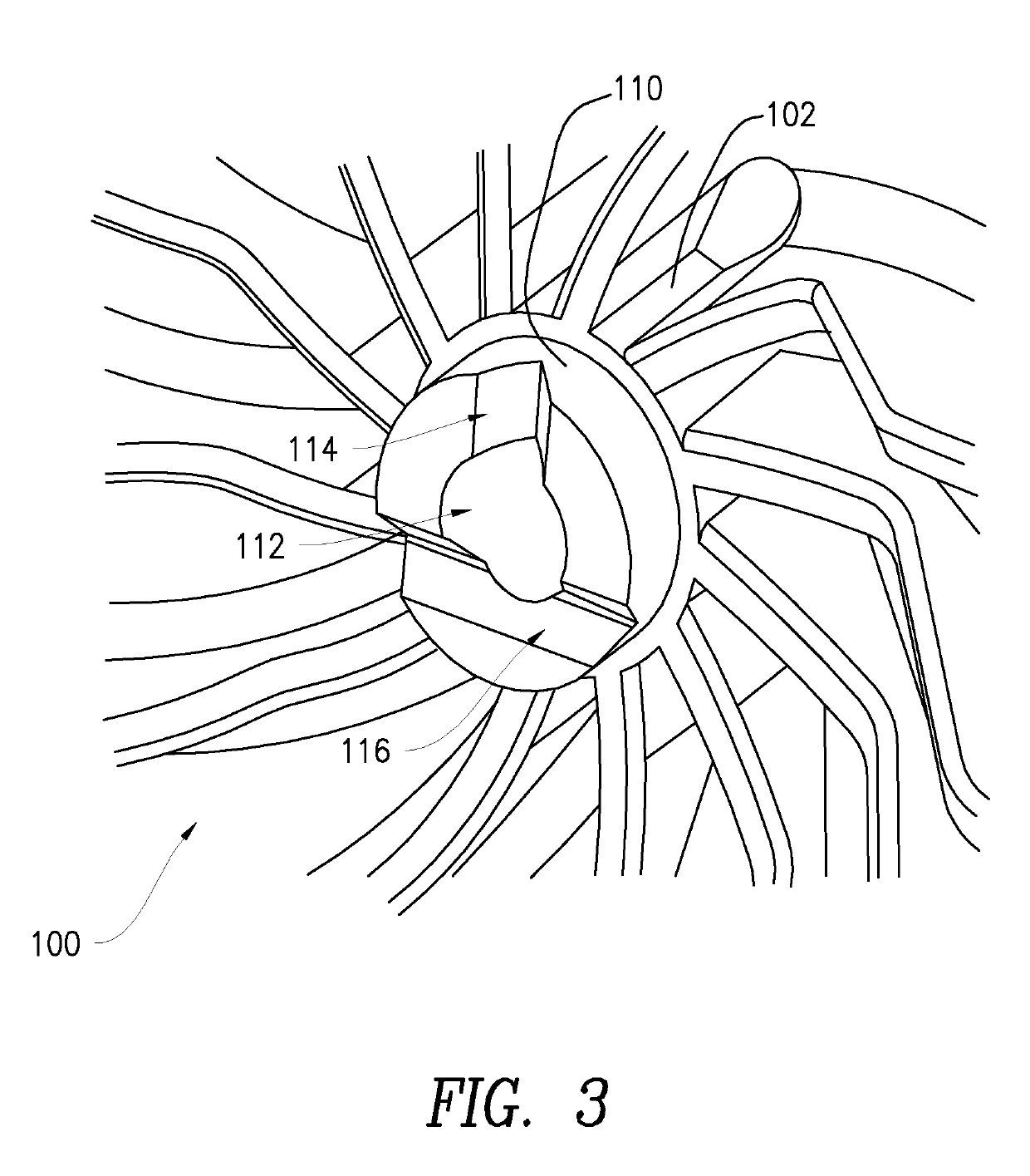
A flange for centering an impeller on a motor shaft includes a central bore for receiving a motor shaft, an impeller facing end and a motor bearing facing end formed opposite the impeller facing end, wherein the impeller facing end includes at least one impeller engaging element configured to couple with a flange facing side of the impeller, wherein the flange facing side of the impeller includes at least one flange engaging element complementary to the at least one impeller engaging element of the flange. An assembly including the motor shaft an impeller is disclosed, as well as centering elements for use in repeatably mounting the assembly to an impeller. Methods of determining optimal balance are disclosed.

Description

CROSS-REFERENCE TO RELATED APPLICATIONS[0001]This non provisional application claims the benefit of U.S. Provisional Patent Application No. 62 / 222,299 filed Sep. 23, 2015, the entirety of which is incorporated herein by reference.FIELD OF THE INVENTION[0002]The invention relates to impellers and in particular to devices and methods for mounting impellers on a motor shaft.BACKGROUND[0003]Many commercially available products such as leaf blowers, blenders, etc. use small motors having an impeller mounted to a rotor. Vibration in such devices can be unpleasant, and in some cases, cause injury to the operator or damage to the device itself when excessive. The vibration in such devices arises principally from rotational imbalance in the impeller assembly. For example, as a rotating assembly revolves at a high speed, such as 15,000 rpm, any imbalance above about 0.6 gram inches causes unpleasant vibration.SUMMARY OF THE INVENTION[0004]The prior art of mounting impellers to motor shafts us...

Claims


Application Information

Patent Timeline
IPC IPC(8): F04D29/04F04D29/20F04D29/05F04D29/22F04D29/053F04D29/043F04D29/62F04D29/28
CPCF04D29/624F04D29/043F04D29/628F04D29/22F04D29/28F04D29/053F04D29/20F04D29/263
Inventor FREAKES, ANTHONY
Owner CONNECTING PRODS
Learn More