Contact tip assembly for a welding torch

a welding torch and contact technology, applied in the direction of welding apparatus, electrode supporting devices, manufacturing tools, etc., can solve the problems of cost and time savings, and achieve the effect of facilitating the transition and facilitating quick release and installation

Inactive Publication Date: 2007-09-13
ILLINOIS TOOL WORKS INC
View PDF10 Cites 47 Cited by
  • Summary
  • Abstract
  • Description
  • Claims
  • Application Information

AI Technical Summary

Benefits of technology

[0009] Therefore, there exists a need for improved contact tip assemblies for welding devices, particularly for facilitating the transition between gas shielded and gasless welding.
[0010] In accordance with certain embodiments, the present invention provides a securement member for securing a contact tip to a welding torch assembly. The exemplary securement member has a channel extending axially therethrough, and has an internal shoulder that extending into this channel. This internal shoulder abuts against

Problems solved by technology

This interchangeability allows the for using essentially the same welding torch assembly for

Method used


Image

  • Contact tip assembly for a welding torch
  • Contact tip assembly for a welding torch
  • Contact tip assembly for a welding torch

Examples


Embodiment Construction

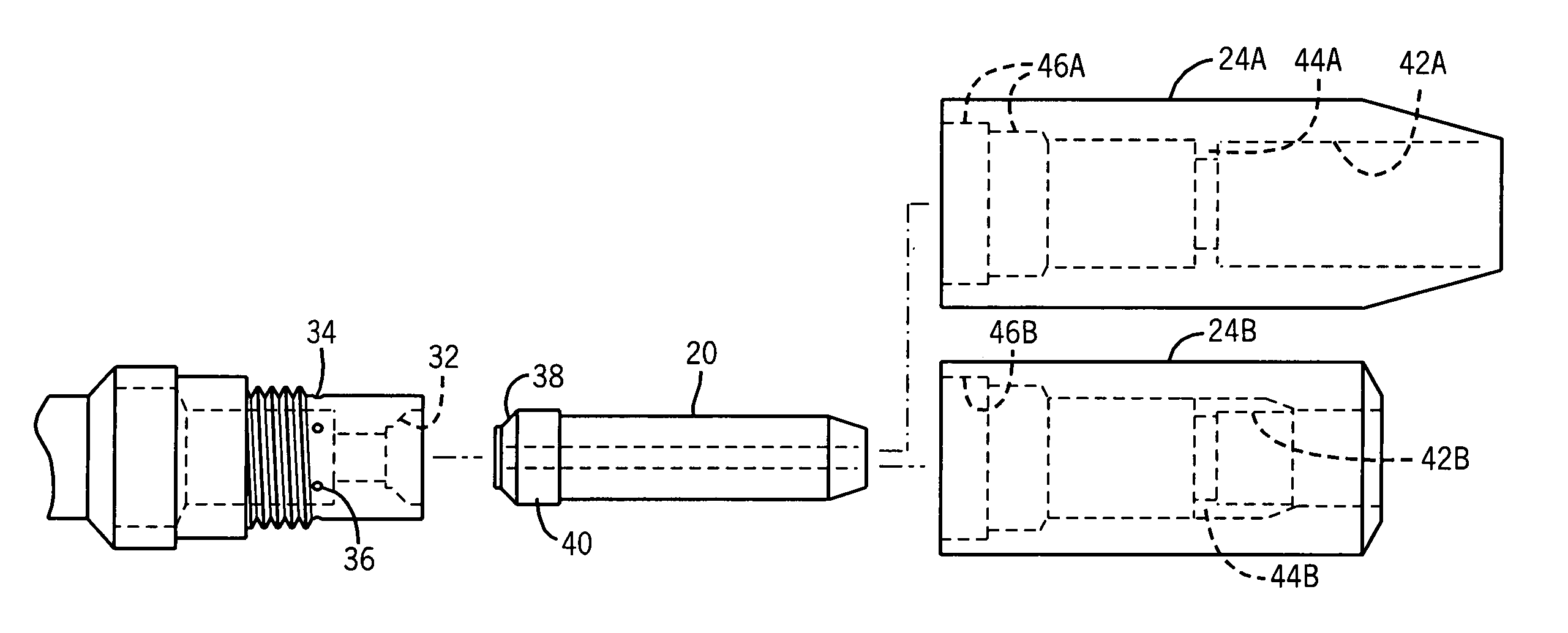
[0019] As discussed in detail below, embodiments of the present invention provide a securement member for securing a contact tip with respect to a welding torch assembly. Advantageously, the securement member captures a contact tip to secure it with respect to torch assembly and, moreover, blocks the egress of shielding material from a diffuser to which the securement member is coupled. Accordingly, a welding torch assembly can be quickly adapted for use with a wire electrode that benefits from a shielding material or for use with a gasless wire electrode that does not employ a shielding material.

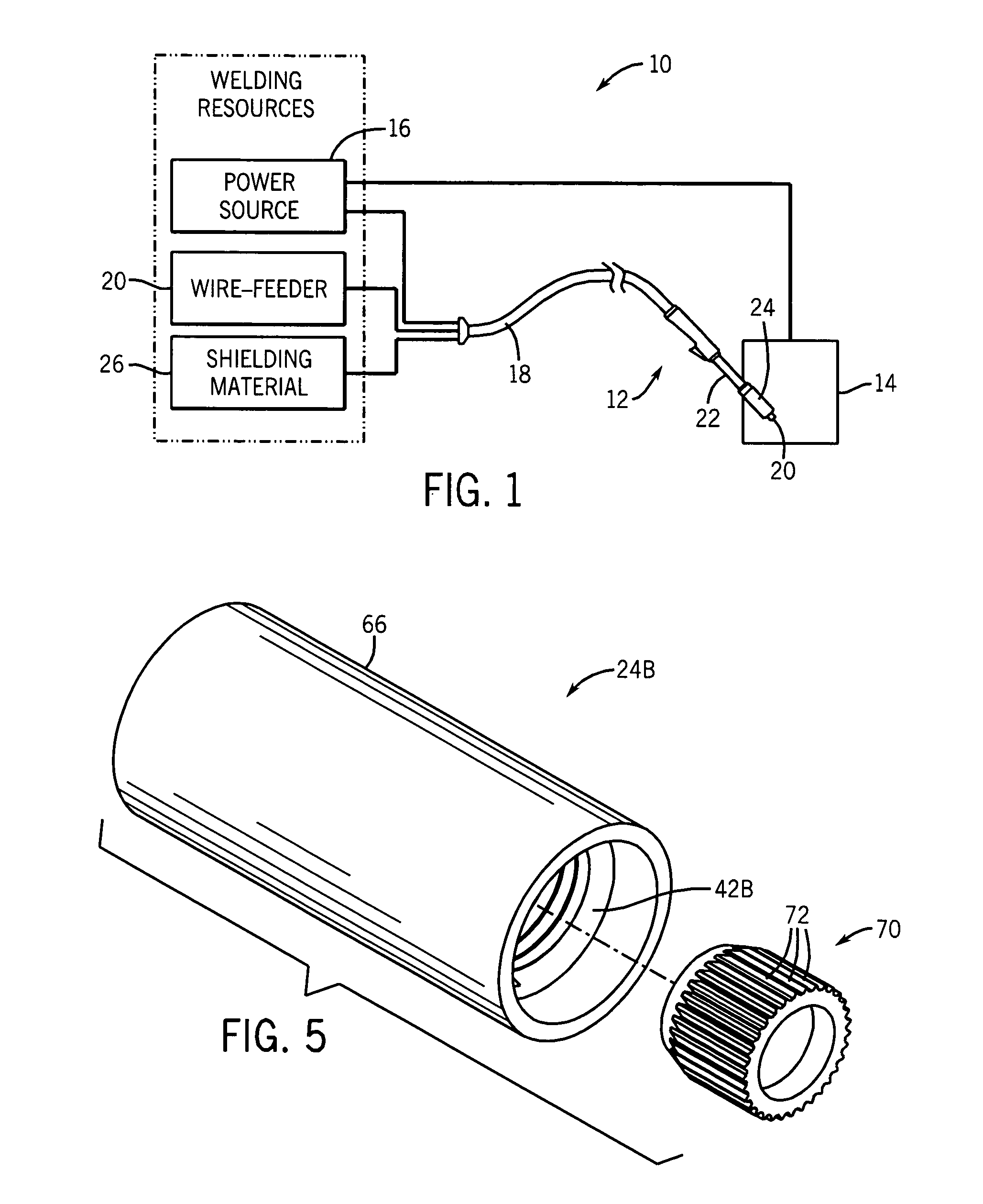
[0020]FIG. 1 illustrates an exemplary wire-feed welding system 10 that incorporates such a securement member. Prior to continuing, however, it is worth noting that the following discussion merely relates to exemplary embodiments of the present technique. As such, the appended claims should not be viewed as limited to those embodiments described herein.

[0021] The exemplary welding system 1...


PUM

PropertyMeasurementUnit
Electrical conductivityaaaaaaaaaa
Diameteraaaaaaaaaa
Widthaaaaaaaaaa

Abstract

A securement member for securing a contact tip to a welding torch assembly is provided. A channel extends axially therethrough and has an internal shoulder that extends into this channel. This internal shoulder abuts against a shoulder on the contact tip, capturing the contact tip between the shoulder and a seating surface on the diffuser and securing the contact tip in the torch assembly. The contact tip is securely seated without threading engagement, facilitating quick release and installation. The exemplary securement member couples to the diffuser such that the egress of fluid from the diffuser is blocked when used for gasless welding. This blocking allows a user to leave the diffuser secured to the welding torch when a gasless electrode is in use.

Description

BACKGROUND [0001] The present invention relates generally to a tip assembly for a welding torch and, particularly, to a tip assembly for a wire feed welding system. [0002] A common metal welding technique employs the heat generated by electrical arcing to transition a workpiece to a molten state, followed by addition of metal from a wire or electrode. One technique that employs this arcing principle is wire-feed welding. At its essence, wire-feed welding involves routing welding current from a power source into an electrode that is brought into close proximity with the workpiece. When the electrode is sufficiently close to the work piece, current arcs from the electrode to the workpiece, completing a circuit and generating sufficient heat to melt and weld the workpiece. Often, the electrode is consumed and becomes part of the weld itself. Thus, new wire electrode is advanced, continuously replacing the consumed electrode and maintaining the welding arc. If the welding device is prop...

Claims


Application Information

Patent Timeline
IPC IPC(8): B23K9/28
CPCB23K9/295
Inventor DINGELDEIN, MATT
Owner ILLINOIS TOOL WORKS INC
Why Eureka
Try Eureka