
Cover plate and adaptor

a technology of adaptor and cover plate, which is applied in the direction of door/window fittings, fastening means, lock casings, etc., can solve the problems of door damage, door damage, and the area in which the handle is installed becoming too damaged to receive a new handle, and achieve the effect of reducing the size of the apertur

Inactive Publication Date: 2007-09-13
TNBT HLDG
View PDF0 Cites 5 Cited by
  • Summary
  • Abstract
  • Description
  • Claims
  • Application Information

AI Technical Summary

Benefits of technology

[0033] Preferably, the first and second cut-outs are configured so as to be suitable for installation of one or more kinds of handle. The first and second cut-outs may be configured to receive protrusions of the handle in order that the handle be installed. The first and second cut-outs may assist to seat the handle in the door.

Problems solved by technology

It may be the case that when the lock was being broken or forced that the area into which the handle is installed becomes too damaged to receive a new handle.
If a handle has been installed incorrectly damage may occur to the door in the area where the handle is to be installed.
In these situations the cover plate can act to reinforce the area for receipt of the handle and provide means for the handle to be secured in the door, which otherwise would not be possible.
Also, use of a cover plate may be the only option, other than replacing the whole door, if the area of the door where a handle is to be installed has been seriously damaged (perhaps through criminal damage, an accident or through incorrect installation of a handle or other door furniture), the door being otherwise still serviceable.
Doors are expensive and laborious to install and it is undesirable to replace an entire door when it is only the handle, turning mechanism or locking mechanism that a person wishes to replace, for practical or aesthetic reasons.
In order that a handle be replaced a person can be limited to choosing a handle or handle-turning mechanism requiring the same size aperture, cut-out layout and backset as previously installed.
Clearly this is undesirable, as the person may be limited to choosing a handle from the same manufacturer as the handle previously installed.
In this case, it is likely that the finished look of the installed handle will not be aesthetically pleasing, and the handle may not be fixed securely in the door.
Clearly, all these changes to a door are undesirable.
Making an aperture, or adapting an existing aperture in the door is time consuming and costly and may lead to unsightly damage to the door.
A cover plate may already be installed on a door if the door has been damaged through an accident, criminal damage or through the incorrect installation of a handle.

Method used


Image

  • Cover plate and adaptor
  • Cover plate and adaptor
  • Cover plate and adaptor

Examples


Embodiment Construction

[0057] The invention will now be described in connection with a non-limiting preferred embodiment with reference to the accompanying drawings.

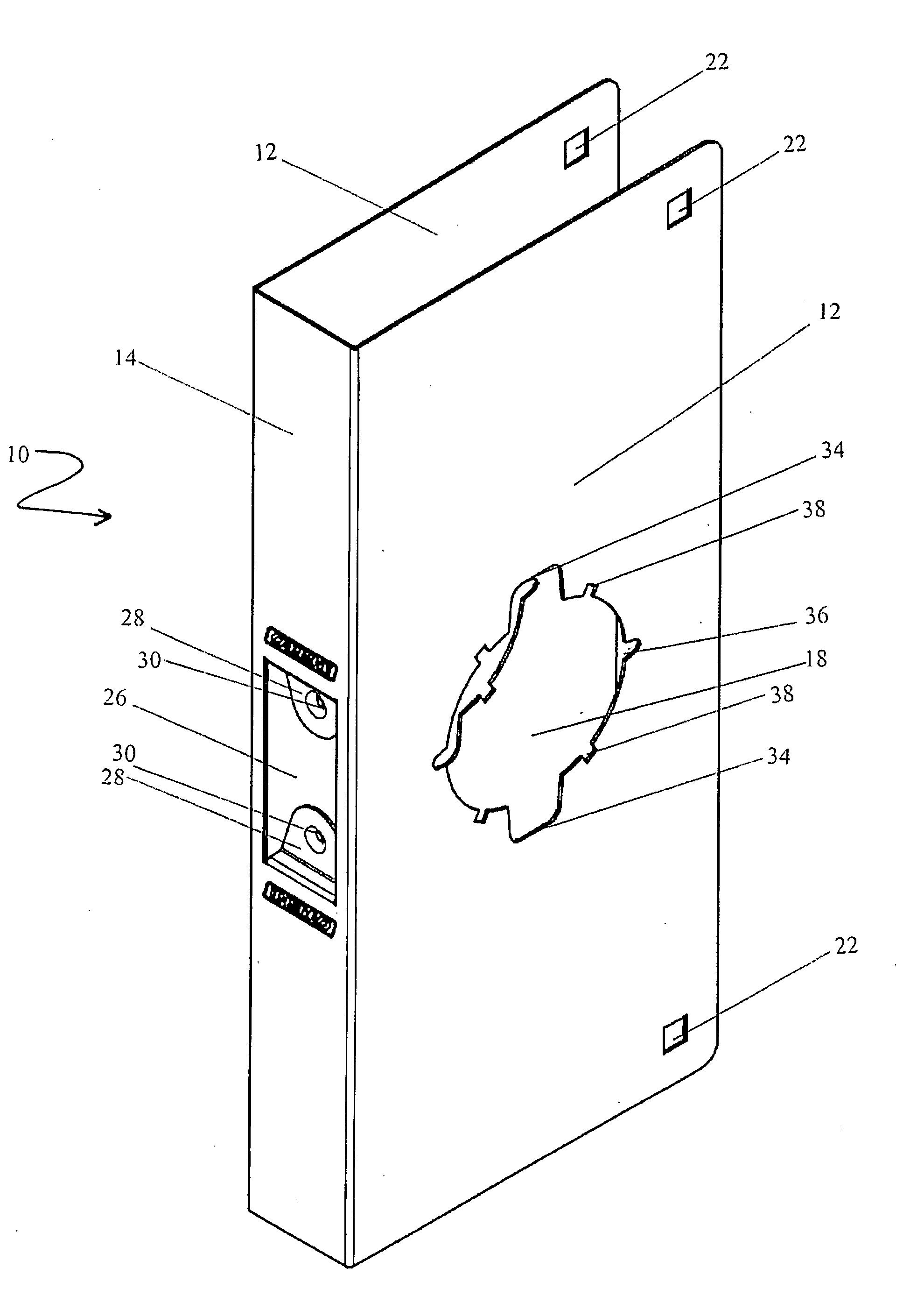
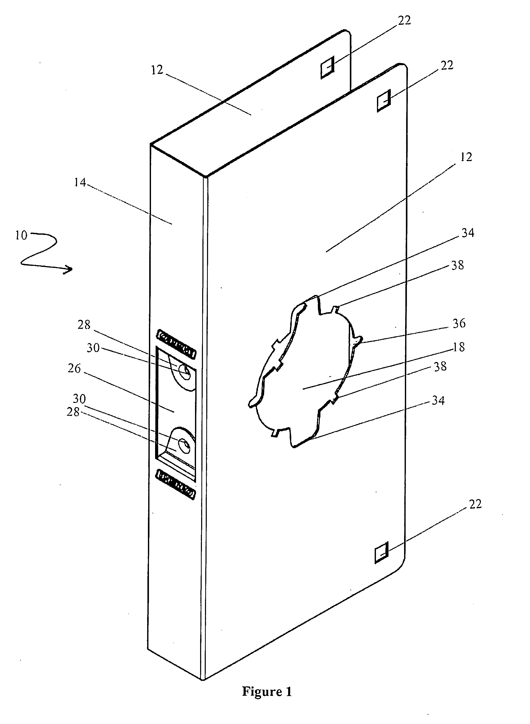
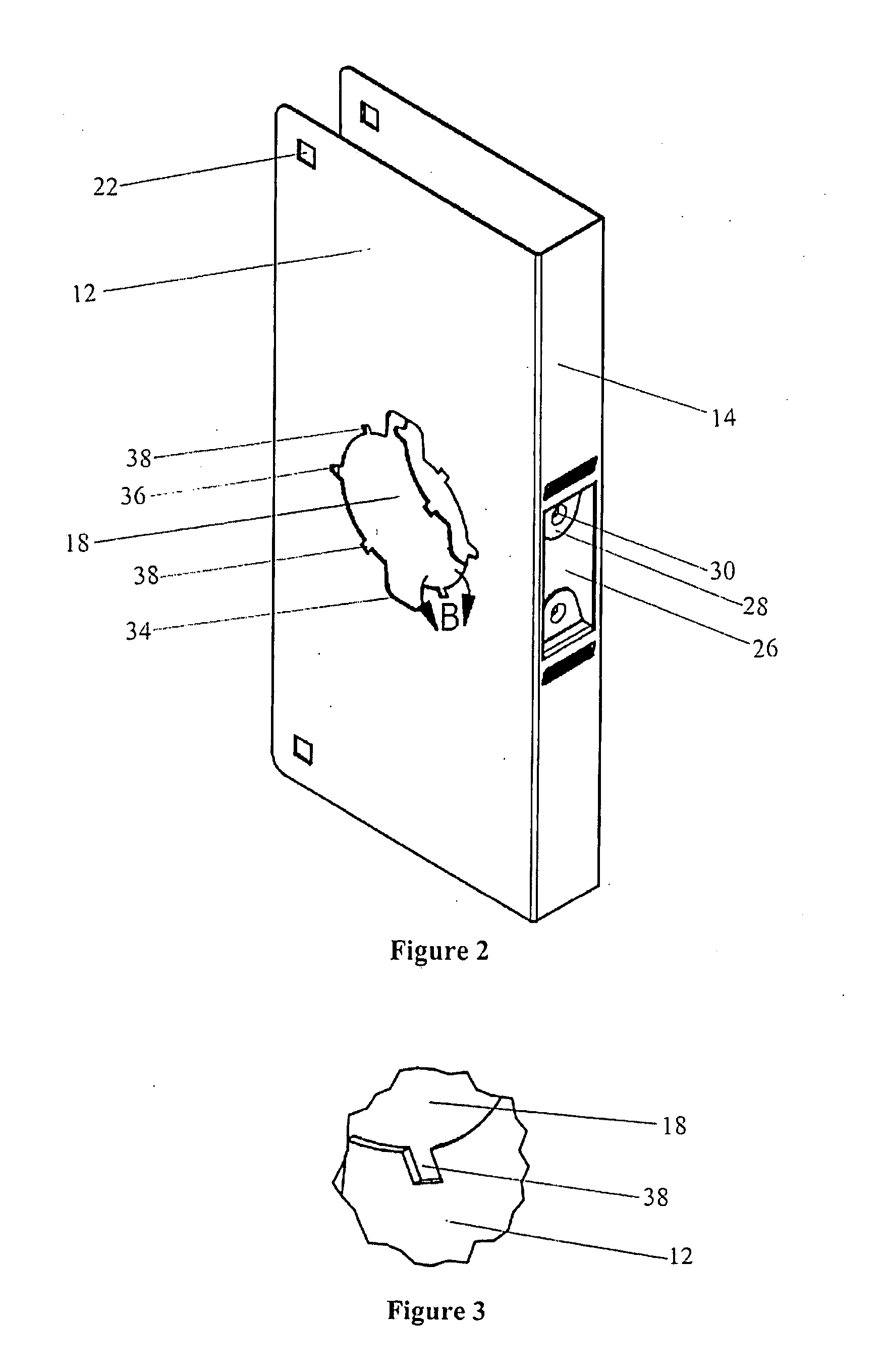
[0058] Referring to FIGS. 1 to 4, cover plate 10 has a pair of opposed flanges 12 joined, one to the other, by spine 14. Spine 14 is configured to maintain flanges 12 in a spaced apart configuration suitable for installation around the edge of door 16 (refer FIG. 9). The width of spine 14 may be any suitable width corresponding to the thickness of door 16 (refer FIG. 9) to which cover plate 10 is to be installed. Typical widths of spine 14 include, but are not limited to, 32 mm, 35 mm, 40 mm, and 45 mm. Although flanges 12 are illustrated as rectangular shapes, any suitable shape may be used. Similarly, spine 14 is illustrated as an elongate rectangular shape but any suitable shape can be used. Spine 14 need not be a solid piece and may contain numerous apertures formed of strips, or otherwise.

[0059] Apertures 18 are formed one in each flang...


PUM


Abstract

The invention relates to a cover plate for installing a handle in a door having opposing faces, an aperture communicating from one face to the other and first and second flanges adapted to lie on the opposing faces. Each flange has an aperture, corresponding at least in part with the aperture in the faces, and first cut-outs and optionally second cut-outs. The aperture and the cut-outs enable at least one different handle to be installed. The handle may have a backset distance of 60 mm, 70 mm, 90 mm, 95 mm or 127 mm, for example. The invention also relates to an adaptor for installing a handle in a door having an aperture communicating from one face of the door to another and cut-outs at the aperture. The adaptor is capable of changing the aperture in the door from one suitable for installing one type of handle to one suitable for installation of a different type of handle. The invention also further relates to use of the cover plate with one or more adaptors.

Description

CROSS-REFERENCE TO RELATED APPLICATION [0001] The present application claims the benefit under 35 USC 119 of Australian provisional No. 2006900888, lodged 22 Feb. 2006, incorporated by reference in its entirety for all purposes. TECHNICAL FIELD [0002] This invention relates to a cover plate for use for installing a handle in a door, an adaptor for use for installing a handle in a door and to using an adaptor and a cover plate for replacing a handle in a door with a different handle. BACKGROUND OF THE INVENTION [0003] In modern times there are many different types and kinds of doors on the market having different styles and varying dimensions. Similarly, there are many different decorative styles and forms of door handle which can be chosen to be installed in a door. It is often desired to change the handle applied to a particular door. A person may wish to install a handle with a different turning mechanism, perhaps with an improved opening and closing action. It may be that a perso...

Claims


Application Information

Patent Timeline
Patent Type & Authority Applications(United States)
IPC IPC(8): E05B3/00
CPCE05B3/00E05B9/002E05B63/0056E05B15/02E05B9/08Y10T292/57
Inventor VANGASSELT, MATTHEW
Owner TNBT HLDG
Learn More