LED lighting device and LCD device using the same

a technology of lighting devices and drive circuits, applied in lighting and heating apparatus, process and machine control, instruments, etc., can solve the problems of increasing circuit costs, increasing the number of photo sensors, and difficulty in compensating brightness fluctuations, etc., and achieve stable luminance

Active Publication Date: 2007-09-13
JAPAN DISPLAY INC +1
View PDF6 Cites 102 Cited by
  • Summary
  • Abstract
  • Description
  • Claims
  • Application Information

AI Technical Summary

Benefits of technology

[0010]It is therefore an object of the present invention to provide a technique for not causing brightness fluctuations by a temperature change and not causing brightness in-plane irregularities even if a temperature distribution is generated in the plane.
[0014]The present invention can provide a lighting device whose brightness is not changed by a temperature change so as to output stable luminance. Furthermore, the present invention can realize an LED lighting device in which no in-plane brightness irregularities are caused by a temperature distribution even if the temperature distribution is generated in the plane.

Problems solved by technology

For this, it is difficult to compensate the brightness fluctuations of the plenty of LEDs by the techniques disclosed in the aforementioned JP-A-2005-310997 and the JP-A-2004-199896.
Such a complicated process in turn increases the circuit cost.
Alternatively, a plenty of photo sensors are required and increase of the number of photo sensors increases the production cost.
Moreover, when using light sources of multi-primary colors such as LED for each of the RGB, it is necessary to arrange a color filter for the photo sensor and detect the light of each color, which also increases the production cost.
Accordingly, it is actually difficult to detect the temperatures of all the LEDs in the plane by a single temperature sensor and a plenty of temperature sensors are required, which increases the production cost.

Method used


Image

  • LED lighting device and LCD device using the same
  • LED lighting device and LCD device using the same
  • LED lighting device and LCD device using the same

Examples


embodiment 1

[0041]Detailed explanation will be given on the first embodiment of the present invention with reference to FIGS. 1 to 8.

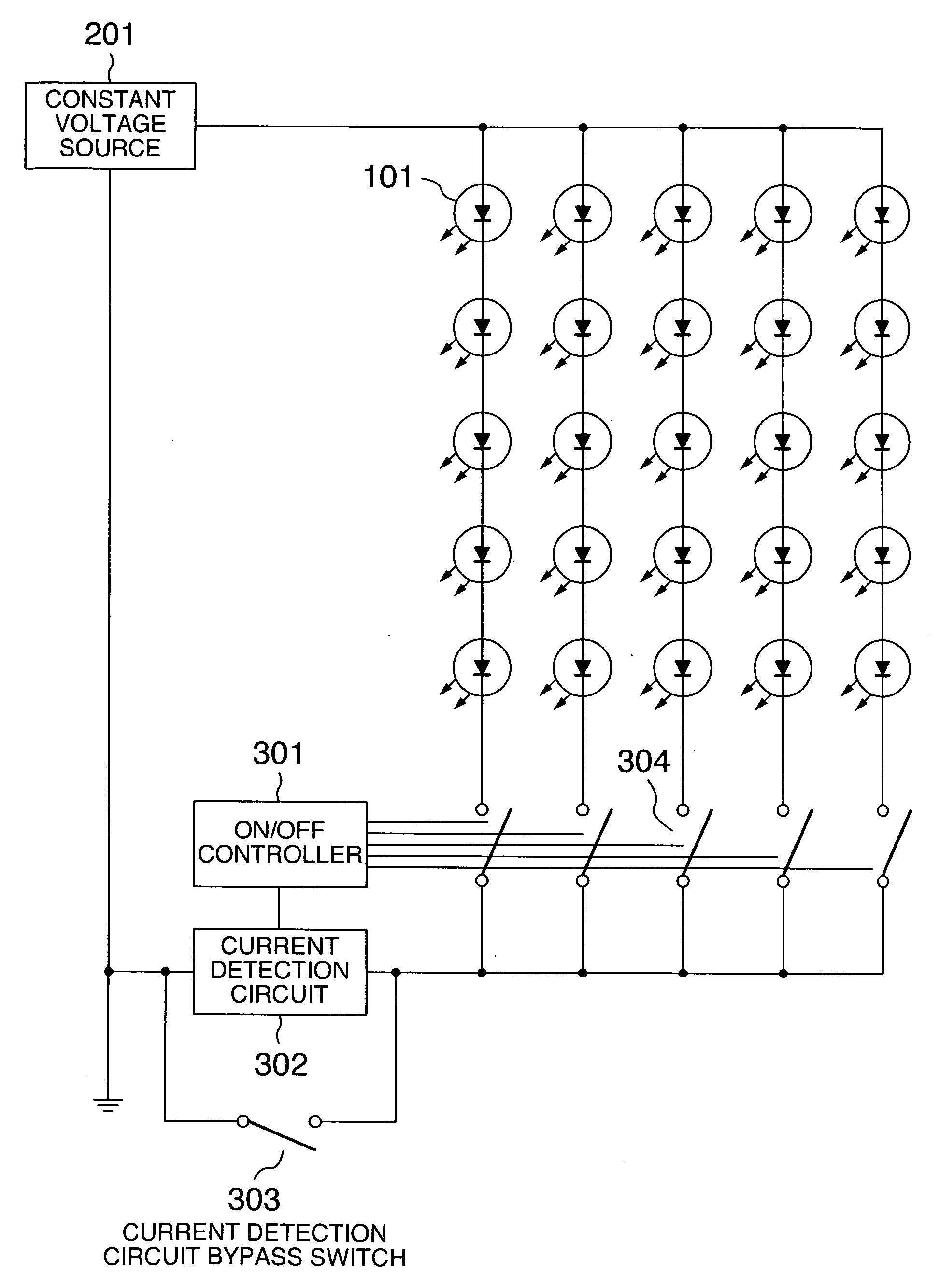
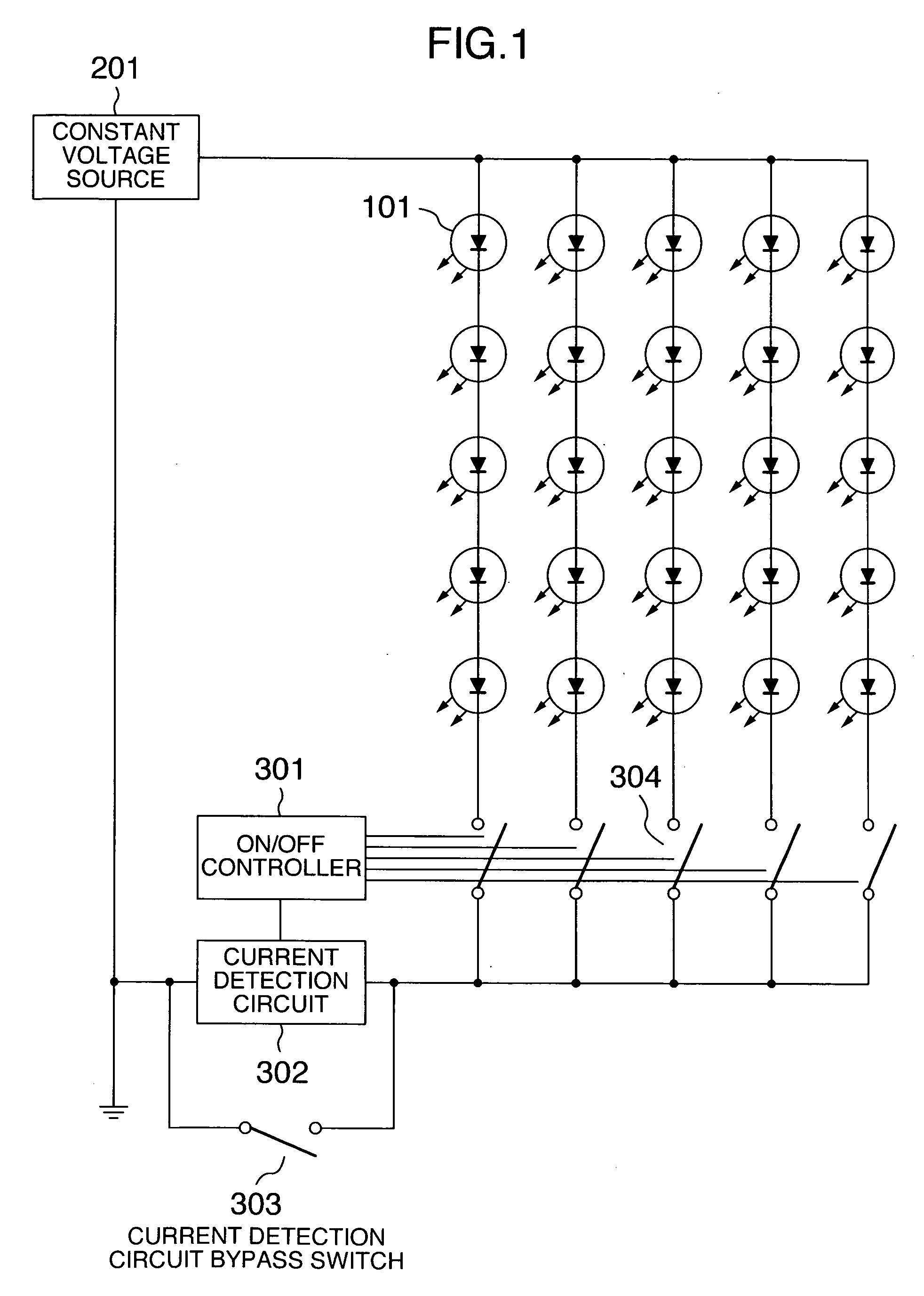
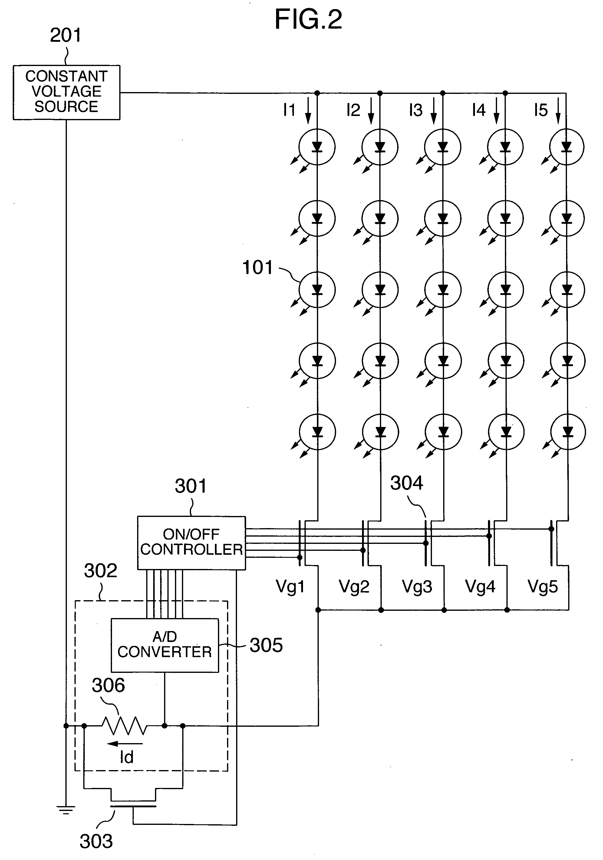
[0042]FIG. 1 shows a concept of a circuit configuration according to the present embodiment. The present embodiment uses five lines, each including five LEDs 101 connected in series and a switch 304 connected in series to the LEDs. The five lines are connected in parallel and each line is driven by a constant voltage source 201.

[0043]A current detector 302 and a bypass switch 303 are arranged at a portion where currents of all the lines are concentrated. With this configuration, it is possible to measure the current values of all the lines by the single current detector 302. That is, only the switch 304 of the line whose current value is to be detected is turned ON and the current flow is measured by the current detector 302. Thus, it is possible to measure a current value of each line.

[0044]Moreover, when no current is to be measured, the bypass switch 303 is tur...

embodiment 2

[0058]Explanation will be given on the second embodiment of the present invention.

[0059]The explanation will be given by referring to FIG. 9.

[0060]The present embodiment shows 12 lines connected in parallel. Each of the lines is connected to an LED 101 and a switch 304 in series. These lines are driven by a constant voltage source 201. The switch 304 of each line is controlled to be ON / OFF by an ON / OFF controller 301. Moreover, the current detector 302 and the bypass switch 303 are arranged in parallel at a position where currents of all the lines are concentrated.

[0061]Furthermore, temperature detection means 310 is provided. A condition table 307 built in the ON / OFF controller 301 decides the ON / OFF period of each line according to the current value of each line and the detection result of the temperature detection means 310.

[0062]By detecting the current of each line, it is possible to adjust the ON / OF period ratio of each line to compensate the brightness fluctuation in the same...

embodiment 3

[0066]Explanation will be given on the third embodiment of the present invention with reference to FIG. 10 and FIG. 11.

[0067]FIG. 10 shows a circuit configuration of the present embodiment. The AC power input is amplified by a transformer 311 and subjected to a rectifier circuit 312 and a smoothing circuit 313 so as to generate a constant voltage. The voltage is adjusted by a switching regulator 314 and used as a constant voltage source 201 of green (G) and blue (B). The G and B voltages are reduced by a step down chopper and the voltage is used as a constant voltage source 201 of red (R). Thus, a plurality of primary colors share the constant voltage source 201, thereby reducing the power cost.

[0068]In this embodiment, three LEDs are connected in series for each of the primary colors and the switch 304 is connected in series in each line. Moreover, two lines are connected in parallel for each of the primary colors.

[0069]The low potential side of each line is commonly connected and ...


PUM


Abstract

An LED lighting device can compensate a brightness change and a color change caused by a temperature change and exhibit an in-plane uniform luminance and color. A lighting device includes: at least one line connected in parallel, a constant voltage source for applying a constant voltage to the line, an ON / OFF controller, and a current detector for measuring a value of current flowing in the line. The line is formed by one or more light-emitting diodes and a switch for turning ON / OFF the current flowing in the light emitting diodes connected in series. According to the current value of each of the lines measured by the current detector, the ON / OFF controller controls the ON / OFF period of the switch of each of the lines.

Description

BACKGROUND OF THE INVENTION[0001]The present invention relates to an LED lighting device drive circuit and an image display device using the same.[0002]Recently, with increase of the light emission efficiency, the light emitting diode (LED) is employed for a lighting device more and more. Especially the LED is tried to be employed for a backlight arranged at the rear surface of a liquid crystal display (LCD) device. As a display method of the liquid crystal display device, in addition to the TN (twisted nematic) as a mainstream, an IPS (in-plane switching) and an MVA (multi-domain vertical alignment) characterized by a wide visual angle are used. These devices form an image by introducing the light of the lighting device arranged on the rear surface of the display unit into a liquid crystal panel capable of controlling the transmittance of the light. As a light source of the lighting device, in addition to the LED, it is possible to use a cold cathode fluorescent light (CCFL), a hot...

Claims


Application Information

Patent Timeline
Patent Type & Authority Applications(United States)
IPC IPC(8): H05B37/00
CPCH05B33/0803H05B33/0815Y02B20/347H05B33/0827H05B33/0866H05B33/0818H05B45/00H05B45/14H05B45/375H05B45/44H05B45/46Y02B20/30H05B45/24
Inventor KONNO, AKITOYOYAMAMOTO, TSUNENORIINUZUKA, TATSUKI
Owner JAPAN DISPLAY INC
Why Eureka
Try Eureka