Illuminator for a dental drill

a technology for dental drills and illumination tubes, applied in dental tools, dental surgery, medical science, etc., can solve the problems of inconvenient illumination methods, high optical fiber costs, and inconvenient use of illumination tubes, and achieve the effects of improving light intensity, power efficiency, and overcoming the short service life of electric bulbs

Inactive Publication Date: 2008-05-08
WANG WEN HAO
View PDF8 Cites 14 Cited by
  • Summary
  • Abstract
  • Description
  • Claims
  • Application Information

AI Technical Summary

Benefits of technology

[0003]The primary objective of the present invention is to provide an illuminator for a dental drill, wherein the light-emitting diode (LED) replaces the traditional electric bulb as the light source to overcome the short service life of the electric bulb and achieve power efficiency and stable brightness.
[0004]Another objective of the present invention is to provide an illuminator for a dental drill, wherein LED is used as the light source, and the fabrication cost of the illuminator of the present invention is thus lower than that of the traditional illuminator using optical fibers.
[0005]According to a preferred embodiment, the illuminator for a dental drill of the present invention comprises a body, a drill and an illuminator The body has a front end, and the interior of the body is an accommodation room. The drill is installed at the front end of the body. The body also has an opening-located portion, and the opening-located portion has a through-hole. The illuminator further comprises a LED and a cable. The LED is installed in the through-hole and has a light-emitting portion facing outward from the through-hole. One end of the cable is connected to the LED, and the other end extends through the accommodation room and toward the rear end of the body. The illuminator of a dental drill of the present invention can cost-efficiently take the place of the conventional illuminator that uses expensive optical fibers to conduct light. Further, the LED used by the present invention has a service life much longer that that of the conventional electric bulb.

Problems solved by technology

However, such an illumination method inconveniences the dentist because light is apt to be blocked.
The abovementioned scheme can solve the illumination problem of a dental drill, but the optical fiber is pretty expensive.
Further, the dental drill needs to have an extra sleeve to accommodate the optical fibers 2 and lead the optical fibers 2 to the front end of the drill 1; thus, the structure thereof becomes more complicated, and the fabrication cost thereof increases.
An electric bulb 3 is used as the light source in the scheme, but the service life of the electric bulb 3 is limited.
Furthermore, as the electric bulb 3 is installed inside the body of the dental drill and at the terminal of the optical fibers 2, the replacement of the electric bulb 3 is not so easy.

Method used


Image

  • Illuminator for a dental drill
  • Illuminator for a dental drill
  • Illuminator for a dental drill

Examples


Embodiment Construction

[0010]The technical contents of the present invention are to be described in detail in cooperation with the drawings below.

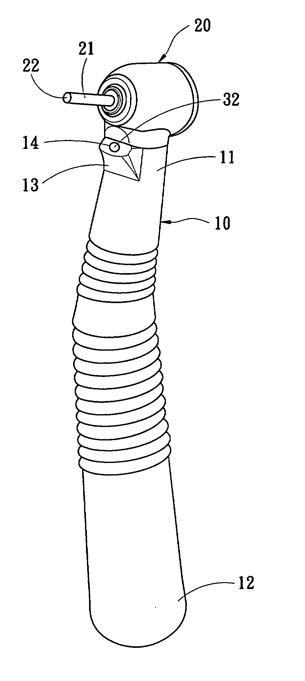
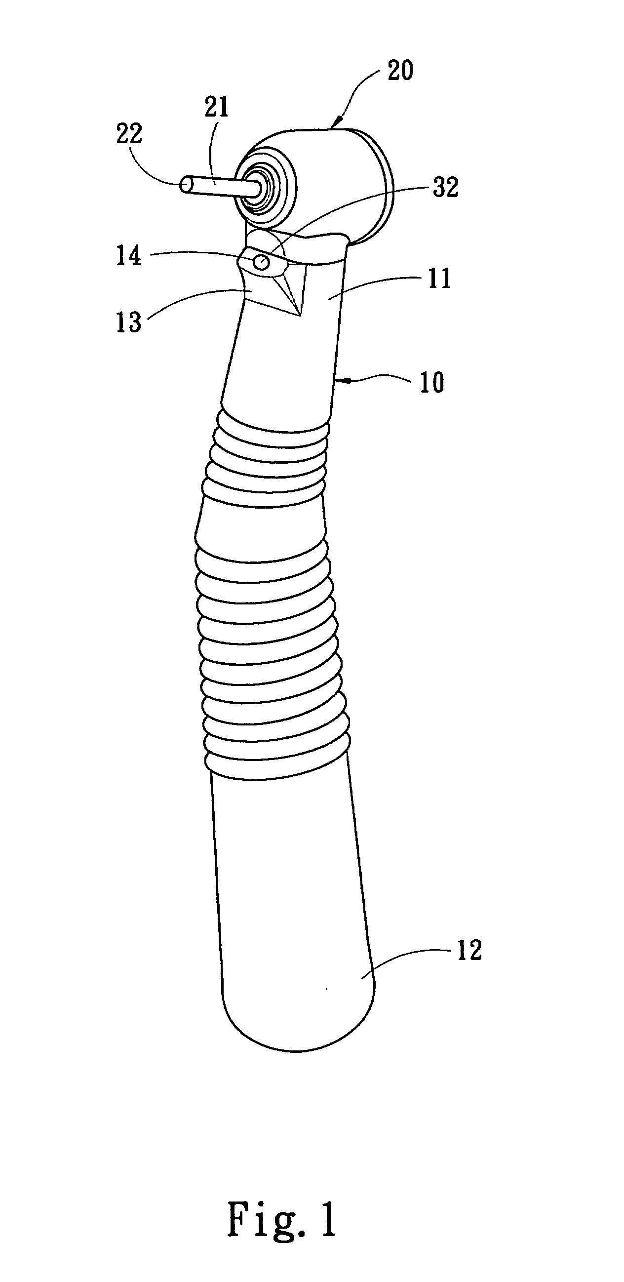
[0011]Refer to FIG. 1 and FIG. 3 respectively a perspective view and a sectional view of a preferred embodiment of the present invention. In this preferred embodiment, the illuminator for a dental drill of the present invention comprises a body 10 having a front end 11 and a rear end 12 and having an accommodation room 15 thereinside, a drill 20 installed at the front end 11 of the body 10, and an illuminator having a light-emitting diode (LED) 30 and a cable 31. The body 10 further has an opening-located portion 13, and the opening-located portion 13 has a through-hole 14. The LED 30 is installed in the through-hole 14 and has a light-emitting portion 32 facing outward from the through-hole 14. One end of the cable 31 is connected to the LED 30, and the other end extends through the accommodation room 15 and toward the rear end 12 of the body 10. The drill 20 h...


PUM


Abstract

The present invention discloses an illuminator for a dental drill, which comprises a body having a front end and a rear end and having an accommodation room thereinside, a drill installed at the front end of the body, and an illuminator having a light-emitting diode (LED). The body further has an opening-located portion, and the opening-located portion has a through-hole. The LED is installed in the through-hole and has a light-emitting portion facing outward from the through-hole. The present invention adopts a LED as the light source and is simpler and cheaper than the conventional illuminator using an electric bulb or optical fibers.

Description

FIELD OF THE INVENTION[0001]The present invention relates to an illuminator, particularly to an illuminator for a dental drill.BACKGROUND OF THE INVENTION[0002]In addition to high precision and sophisticated skill, a dentist also needs appropriate illumination for the oral cavity in a dental therapeutic process, especially in a dental-polishing or dental-drilling process. Traditionally, the illumination is implemented with an external light source. As the dentist usually has to hold a dental mirror with one hand and take a dental drill with the other hand, the external light source is placed inside the oral cavity of the patient with a frame. However, such an illumination method inconveniences the dentist because light is apt to be blocked. Therefore, a U.S. Pat. No. 5,049,070 disclosed a dental drill, wherein a bundle of optical fibers 2 is used to guide light to the front end of the drill 1 to compensate the external light source and directly illuminate the oral cavity of the pati...

Claims


Application Information

Patent Timeline
Patent Type & Authority Applications(United States)
IPC IPC(8): A61C1/00
CPCA61C1/088
Inventor WANG, WEN-HAO
Owner WANG WEN HAO
Why Eureka
Try Eureka