Current Measurement Apparatus

Active Publication Date: 2007-09-13
LEM HEME
View PDF9 Cites 32 Cited by
  • Summary
  • Abstract
  • Description
  • Claims
  • Application Information

AI Technical Summary

Benefits of technology

[0019] Preferably the Rogowski coil comprises a single insulated wire which provides a central conductor and a coil and more preferably comprises a single homogeneous insulated wire which

Problems solved by technology

Any deviation from this closed loop results in an incomplete line integral, as defined by Ampere's Theorem, and therefore, a degraded accuracy in measurement of the curr

Method used


Image

  • Current Measurement Apparatus
  • Current Measurement Apparatus
  • Current Measurement Apparatus

Examples


Embodiment Construction

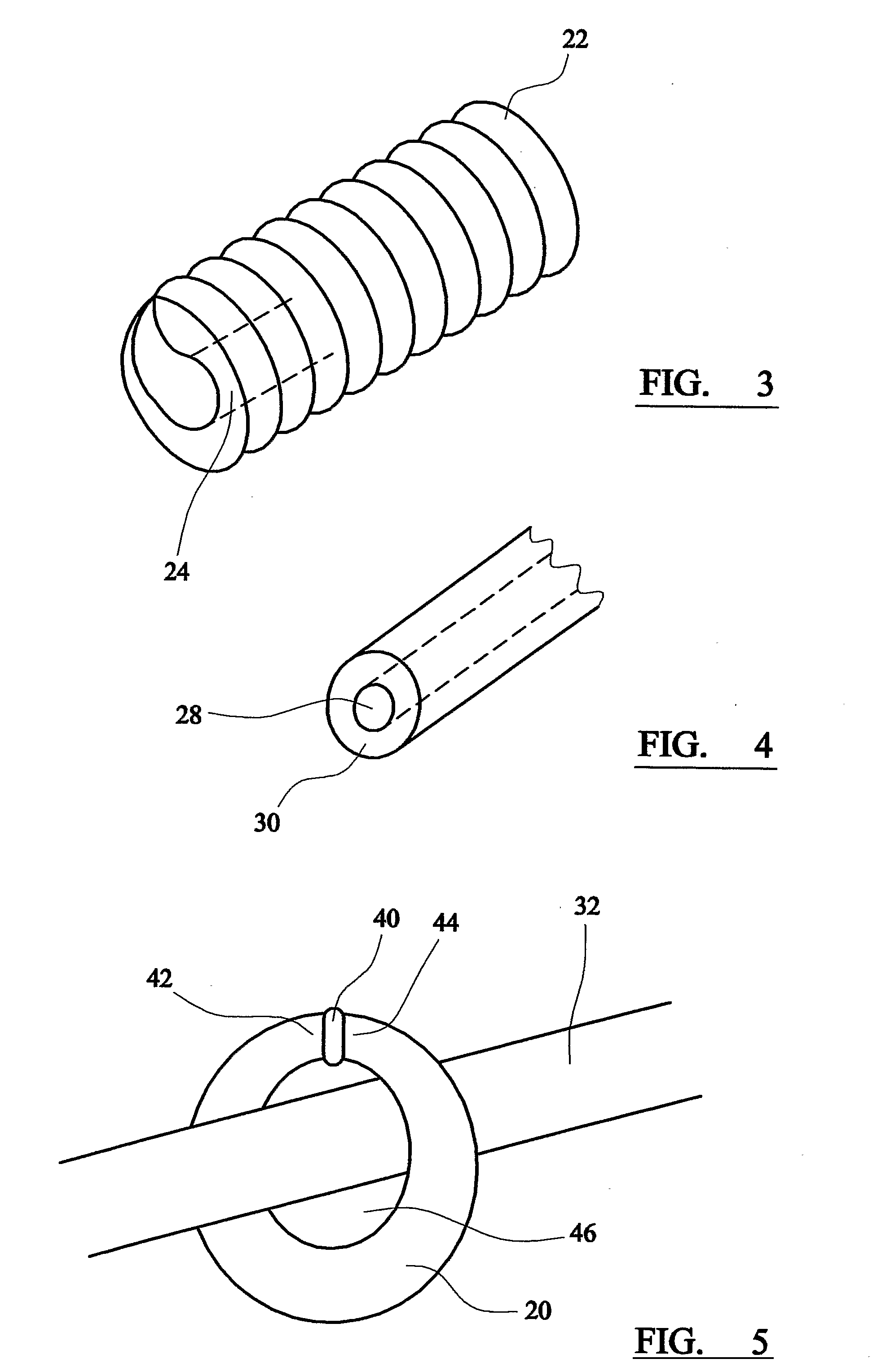
[0050] As shown in FIG. 3, a preferred embodiment of electric current measurement apparatus comprises a Rogowski coil 20 comprising a wire or conductor which forms a coil 22 and returns through the coil 22 as a central conductor 24. The coil 22 and the central conductor 24 are formed from a single conductor or wire and, therefore, no electrical join (for example, a solder join or crimp) is required at the end of the Rogowski coil 20. Such joints are required in prior art Rogowski coils.

[0051] The wire 28 used to form the coil 22 and the central conductor 24 is insulated prior to forming the Rogowski coil 20, as shown in FIG. 4. The wire is coated with the required amount of insulation 30 or insulation material. The wire is not merely coated with a coating material since this would not provide the necessary insulation characteristics. The insulated coating 30 on the wire provides better insulation between individual coils and also helps provide a more even spacing between coils rela...


PUM


Abstract

The current measurement apparatus comprises a Rogowski coil 20 comprising a wire or conductor which forms a coil 22 and returns through the coil 22 as a central conductor. The coil 22 and the central conductor are formed from a single conductor or wire and, therefore, no electrical join (for example, a solder join or crimp) is required at the end of the Rogowski coil. The wire 28 used to form the coil 22 and the central conductor 24 is insulated prior to forming the Rogowski coil. The insulated coating 30 provides better insulation between individual coils and also helps to provide a more even spacing between the coils.

Description

FIELD OF THE INVENTION [0001] The present invention relates current measurement apparatus and a method of measuring current and, in particular, pulsed or alternating currents. BACKGROUND TO THE INVENTION [0002] The Rogowski Coil was invented by Chattock in the 1880's (Chattock A. P. On a magnetic potentiometer Philos Mag., 1887 pp 94-96). It is a flexible solenoid with a co-axial return conductor and is used in non-intrusive manner to sense the magnetic field generated by a current carrying conductor by encircling said conductor. The output of the Rogowski Coil is a voltage proportional to the derivative or rate of change of the current being measured. Means need to be provided to integrate this voltage output to create a voltage output proportional to the current being measured. [0003] Based on Ampere's theorem, if a solenoid of length 1 having N turns of area A, and a pitch of n=N / 1, encircles the current carrying conductor perpendicularly with a radius R=1 / 2π centred around said ...

Claims


Application Information

Patent Timeline
IPC IPC(8): G01R15/18
CPCG01R15/181G01R15/18
Inventor EBENEZER, DESMONDZWOLINSKI, ALBERT
Owner LEM HEME
Why Eureka
Try Eureka