
Building alarm system with synchronized strobes

Inactive Publication Date: 2007-09-13
STEWART ALBERT J +1
View PDF36 Cites 0 Cited by
  • Summary
  • Abstract
  • Description
  • Claims
  • Application Information

AI Technical Summary

Benefits of technology

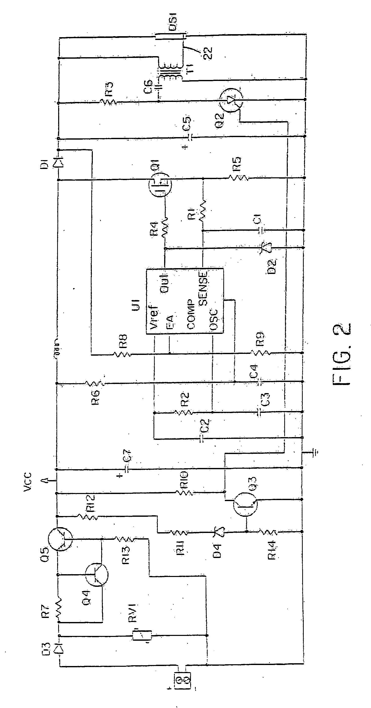
[0008] In order to avoid overcharging of the capacitor as a strobe waits for the firing signal, each strobe further includes a voltage sensor for disabling the charging circuit when the capacitor reaches a firing voltage level.

Problems solved by technology

Unfortunately, the strobes at the higher intensity levels have been reported to trigger epileptic seizures in some people.

Method used


Image

  • Building alarm system with synchronized strobes
  • Building alarm system with synchronized strobes
  • Building alarm system with synchronized strobes

Examples


Embodiment Construction

[0014] A description of preferred embodiments of the invention follows.

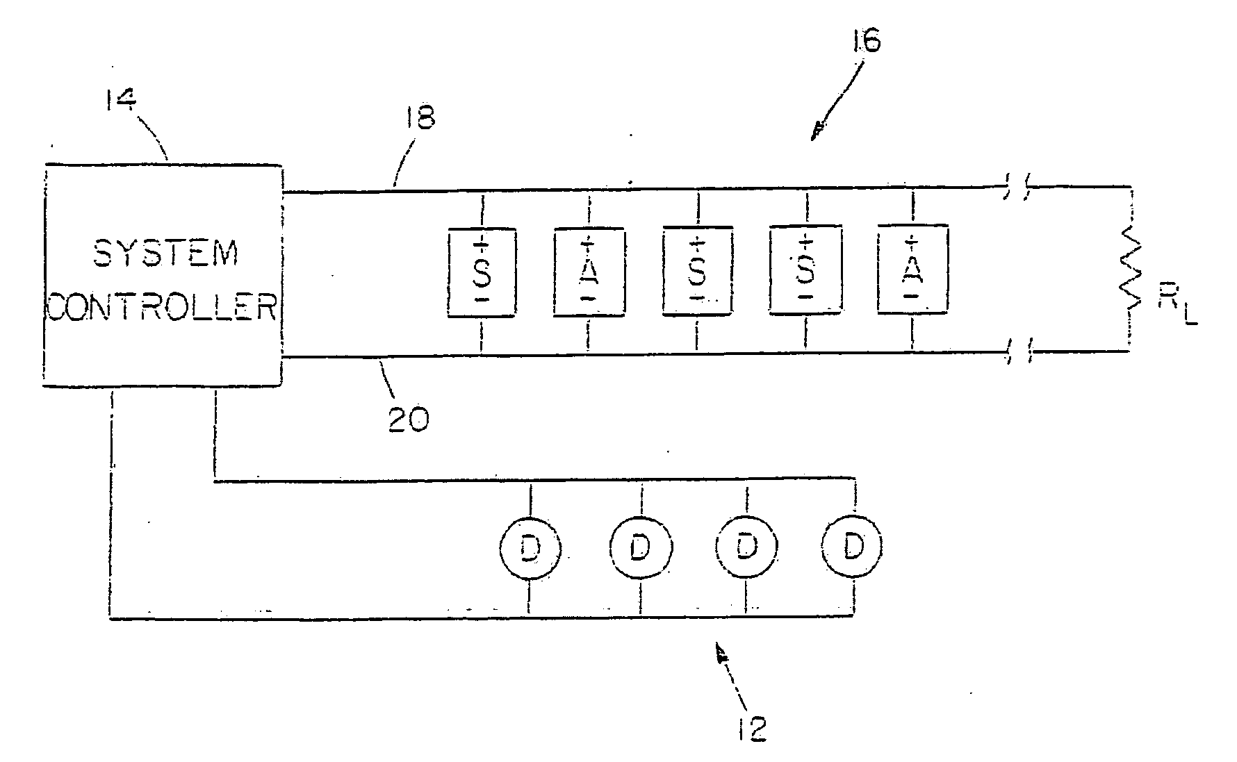
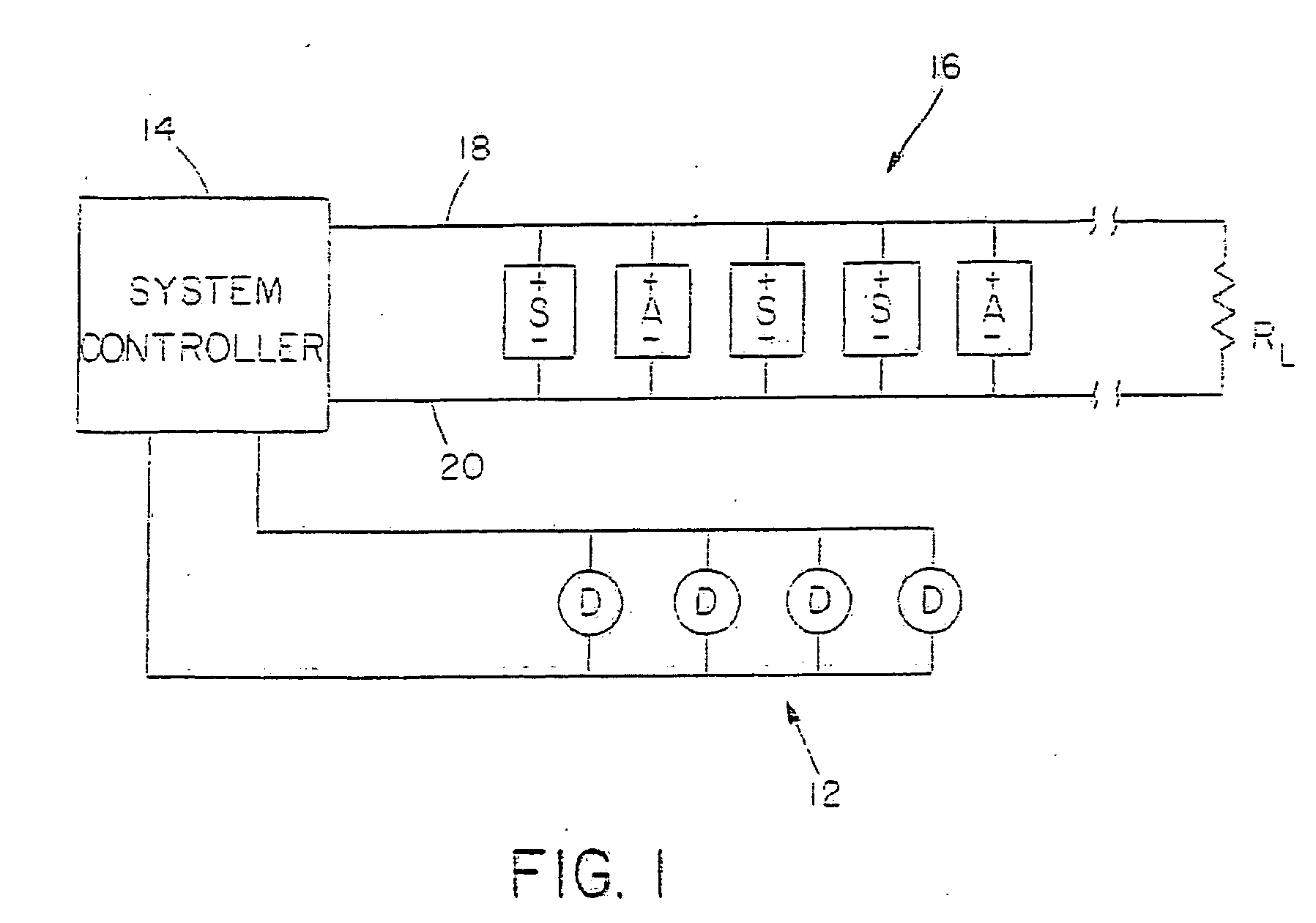
[0015] A system embodying the present invention is illustrated in FIG. 1. As in a conventional alarm system, the system includes one or more detector networks 12 having individual fire detectors D which are monitored by a system controller 14. When an alarm condition is sensed, the system controller signals the alarm through at least one network 16 of alarm indicators. The alarm indicators may include any variety of audible alarms A and light strobe alarms S. As shown, all of the alarms are coupled across a pair of power lines 18 and 20, and the lines 18 and 20 are terminated at a resistance RL.

[0016] Each of the alarms A and S includes a rectifier at its input which enables it to be energized with only one supply polarity as indicated. When there is no alarm condition, the network 16 may be monitored by applying a reverse polarity DC voltage across the network. Specifically, line 20 would be positive relative ...


PUM


Abstract

In a building fire alarm system, the light strobes of a network of strobes are synchronized to flash simultaneously. Each strobe has a charging circuit to charge a capacitor which discharges through a flash tube. Once a capacitor is charged, the charging circuit is disabled. A synchronization pulse is applied through common power lines to trigger discharge of each strobe capacitor through the flash tube followed by recharging of the capacitor.

Description

RELATED APPLICATIONS [0001] This application is a Continuation Application of U.S. application Ser. No. 11 / 396,296, filed Mar. 31, 2006, which is a Continuation Application of U.S. application Ser. No. 11 / 243,471, filed Oct. 4, 2005, which is a Continuation Application of U.S. application Ser. No. 11 / 077,960, filed Mar. 11, 2005, which is a Continuation Application of U.S. application Ser. No. 10 / 890,817, filed Jul. 14, 2004, which is a Continuation Application of U.S. application Ser. No. 10 / 799,445, filed Mar. 12, 2004, which is a Continuation Application of U.S. application Ser. No. 10 / 642,113, filed Aug. 15, 2003, which is a Continuation Application of U.S. application Ser. No. 10 / 352,374, filed Jan. 27, 2003, now abandoned, which is a Continuation Application of U.S. application Ser. No. 10 / 211,935 filed Aug. 1, 2002, which is a Continuation Application of U.S. application Ser. No. 10 / 040,259, filed Jan. 2, 2002, which is a Continuation Application of U.S. application Ser. No. ...

Claims


Application Information

Patent Timeline
IPC IPC(8): G08B5/00
CPCG08B7/06G08B25/04G08B17/107
Inventor STEWART, ALBERT J.STANLEY, LAWRENCE G.
Owner STEWART ALBERT J
Learn More