Imprint stamper, method for manufacturing the same, recording medium, method for manufacturing the same, information recording/reproducing method, and information recording/reproducing apparatus

a stamper and printing technology, applied in the field of stampers, can solve the problems of increasing noise, recording becomes unstable, and takes more time than according to the latter method, and achieves the effects of reducing the time to manufacture magnetic recording media, and reducing the time to manufactur

Inactive Publication Date: 2007-09-13
KK TOSHIBA
View PDF7 Cites 39 Cited by
  • Summary
  • Abstract
  • Description
  • Claims
  • Application Information

AI Technical Summary

Benefits of technology

[0037] According to the magnetic recording medium manufacturing imprint stamper according to the first configuration of the invention, a pattern suitable to the servo region and a pattern to the data region can be transferred to a magnetic recording medium in a lump. Accordingly, by use of the composite type imprint stamper, a magnetic recording medium can be manufactured more efficiently.
[0038] According to the method for manufacturing a magnetic recording medium manufacturing imprint stamper according to the second configuration of the invention, a master is produced by a servo region master imprint stamper and a data region master imprint stamper, and a composite type medium imprint stamper is produced by use of the master. As a result, the time to produce a magnetic recording medium master having as high recording density and precision as that in the magnetic recording medium according to the sixth configuration of the invention can be shortened on a large scale in comparison with the case where a magnetic recording medium master is produced by an artificial drawing method in the background art.
[0039] According to a magnetic recording medium using a sector servo system according to the third configuration of the invention, a magnetic recording medium having a high-recording-density data region and a high-precision servo region can be provided.
[0040] According to the method for manufacturing a magnetic recording medium according to the fourth configuration of the invention, the first transfer region corresponding to the servo region and the second transfer region corresponding to the data region can be transferred concurrently due to batch transfer using a composite type medium imprint stamper. Magnetic recording media obtained from one and the same master have relative position information between the first transfer region and the second transfer region. Thus, there is an effect that time to manufacture magnetic recording media can be shortened.
[0041] According to the fifth configuration of the invention, in recording / reproducing of a servo region and a data region having relative misregistration, the misregistration is corrected so that recording / reproducing of the recording medium can be achieved with high accuracy and in high recording density.
[0042] According to the sixth configuration of the invention, it is possible to provide information recording / reproducing apparatus by which relative misregistration between a high-accuracy servo region and a high-recording-density data region can be corrected based on positioning signals located in the regions.

Problems solved by technology

Due to thermal fluctuation generated in the single crystals, recording becomes unstable in smaller single crystals which are more affected by the thermal fluctuation.
Therefore, in a small recording cell, recording becomes unstable enough to increase noise.
According to the former method, high precision and high recording density media can be produced, but it takes more time than according to the latter method.
However, a dot-shaped (granular) recording material is not suitable for drawing a minute pattern such as a positioning signal in the servo region.
In addition, when the servo region is drawn, it is difficult to attain higher positioning accuracy by use of a material as large as the recording material in the data region than that of the recording material.
Further, when the self-assembled material is used, there occurs a misalignment or a dimensional divergence in each dot due to fluctuation of the material itself or fluctuation in annealing.
Due to the misalignment or the dimensional divergence, existing self-assembled materials are not suitable for the positioning signal in the servo region which signal needs high accuracy.
That is, according to the existing method for producing a patterned medium using a self-assembled material, it is possible to create a pattern all over the medium, but it is difficult to create a pattern in only a part of the medium or particularly in a region segmented at a minute interval.
As a result, an unnecessary dot appears in the servo region so that the accuracy of the positioning signal in the servo region deteriorates.
Such a material is not suitable for artificial drawing in the following process.
According to the existing techniques, it is therefore difficult to manufacture a magnetic recording medium having a high-density data region and a high-precision servo region.
When a recording medium is manufactured with different methods being applied to the servo region and the data region respectively, there occurs a relative misregistration between the two regions.
The accuracy of this positioning has a limit due to mechanical reproducibility, uneven expansion caused by uneven temperature, mixture of impurities, etc.
Thus, there occurs a misregistration between the servo region formed in the artificial drawing method and the data region formed in the method using a self-assembled material.
However, due to an error caused by the thickness of a layer of the air between the structure and the subject, there is a limit of about 10 μm in the positioning accuracy.
However, due to an error caused by the wavelength of light, there is a limit of about 50 nm in the positioning accuracy.
In conclusion, the limit of about 10 nm or lower in the positioning accuracy cannot be satisfied in either positioning method.
In this case, the relative misregistration occurring among pattern regions cannot be corrected.

Method used


Image

  • Imprint stamper, method for manufacturing the same, recording medium, method for manufacturing the same, information recording/reproducing method, and information recording/reproducing apparatus
  • Imprint stamper, method for manufacturing the same, recording medium, method for manufacturing the same, information recording/reproducing method, and information recording/reproducing apparatus
  • Imprint stamper, method for manufacturing the same, recording medium, method for manufacturing the same, information recording/reproducing method, and information recording/reproducing apparatus

Examples


first embodiment

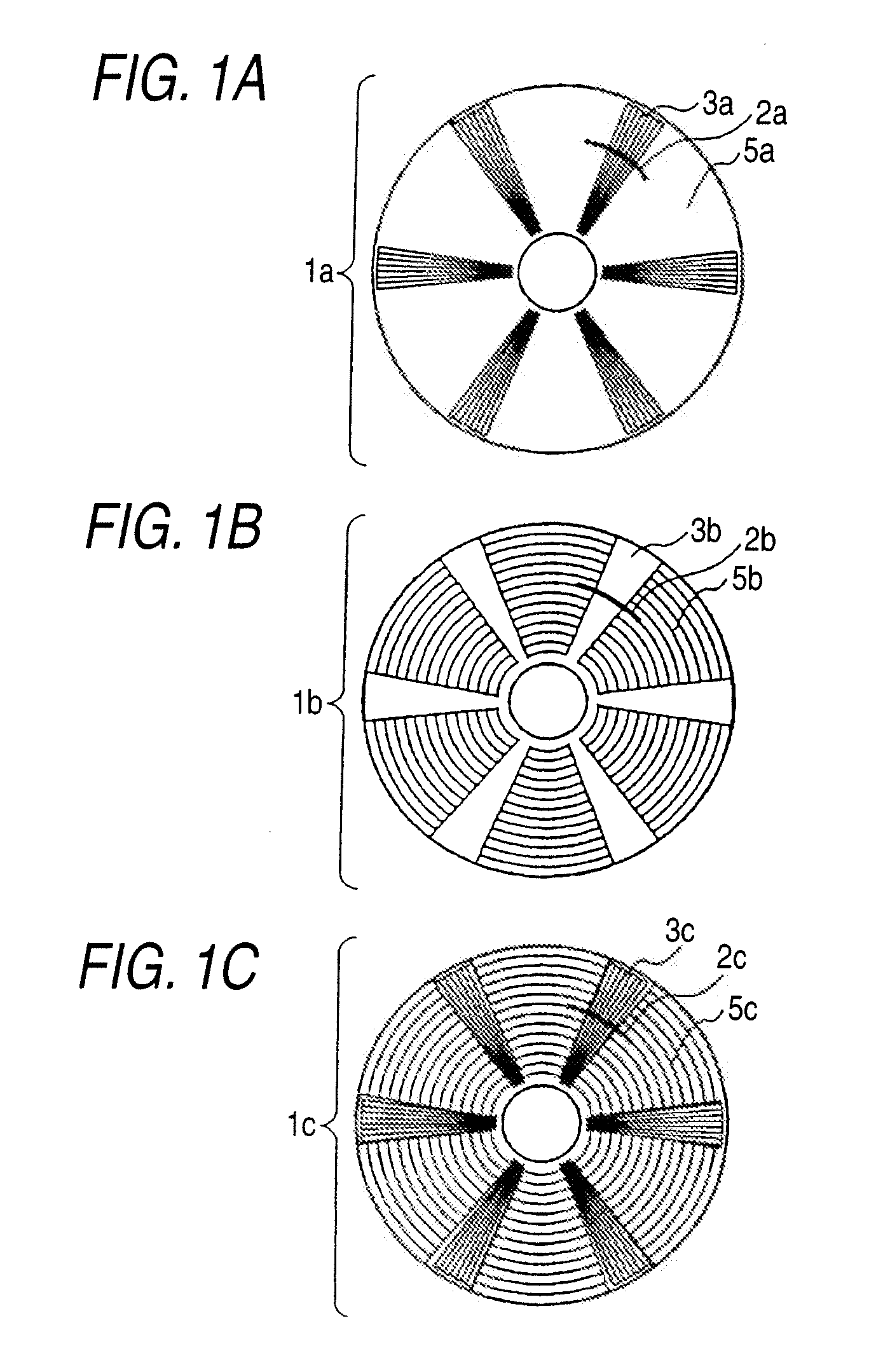
[0066] A first embodiment related to a magnetic recording medium manufacturing imprint stamper according to the first configuration of the invention will be described below with reference to FIGS. 1A and 1B and FIGS. 2A and 2B.

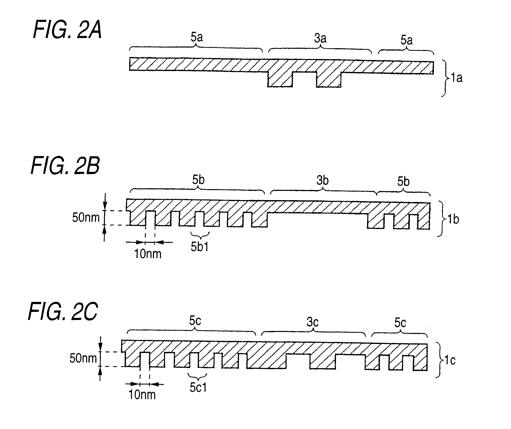
[0067]FIG. 1A is a schematic surface view showing a transfer surface of a servo region imprint stamper 1a. FIG. 1B is a schematic surface view showing a transfer surface of a data region imprint stamper 1b to be paired with the servo region imprint stamper 1a depicted in FIG. 1A. FIGS. 2A and 2B are schematic sectional views showing the imprint stampers in which dot-like recess portions 5b1 are portions corresponding to recording dots in a mold pattern. FIG. 2A is a schematic sectional view showing a portion of the servo region imprint stamper 1a designated by the solid line 2a. FIG. 2B is a schematic sectional view showing a portion of the data region imprint stamper 1b designated by the solid line 2b.

[0068] Each imprint stamper according to this embodiment...

second embodiment

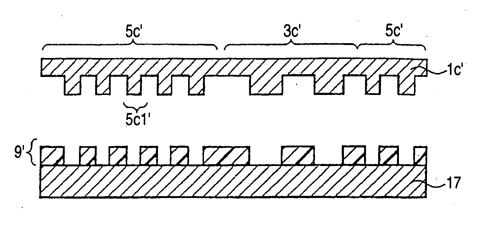
[0091] A second embodiment related to a magnetic recording medium manufacturing imprint stamper according to the second configuration of the invention will be described below with reference to FIGS. 1C and 2C.

[0092]FIG. 1C is a schematic surface view showing a transfer surface of a composite type imprint stamper 1c. FIG. 2C is a schematic sectional view corresponding to FIGS. 2A and 2B, and showing a portion of the composite type imprint stamper 1c designated by the solid line 2c when portions 5b1 corresponding to recording dots in a mold pattern are recess portions.

[0093] As shown in FIG. 1C, the composite type imprint stamper 1c is formed into a disc-like shape and for manufacturing a magnetic recording medium using a sector servo system. Accordingly, as shown in FIG. 1C, first transfer regions 3c corresponding to servo regions of a magnetic recording medium are radial regions running from the axis toward the outer edge. First non-transfer regions 5c corresponding to data region...

third embodiment

[0110] A third embodiment related to a method for manufacturing a magnetic recording medium manufacturing imprint stamper according to the third configuration of the invention will be described below with reference to FIGS. 5A to 5D, 6A to 6C, 7A to 7D and 8A to 8C.

[0111] This embodiment will be described along the method for manufacturing an imprint stamper according to the second embodiment, by way of example. In addition, the composite type medium imprint stamper 1c in the second embodiment is manufactured by use of the servo region master imprint stamper 1a and the data region master imprint stamper 1b in the first embodiment.

[0112] First, a method for manufacturing a master imprint stamper will be described using the servo region master imprint stamper 1a and the data region master imprint stamper 1b by way of example.

[0113] The servo region master imprint stamper 1a is formed as follows. That is, the surface of a stamper material is coated with a resist film. A pattern is d...


PUM

PropertyMeasurementUnit
diameteraaaaaaaaaa
thicknessaaaaaaaaaa
curvature radiusaaaaaaaaaa

Abstract

An imprint stamper for manufacturing a recording medium includes a first transfer region which corresponds to a servo region of a recording medium using a sector servo system and has a pattern with a plurality of quadrilateral recess or protrusion portions formed in a surface thereof, and a second transfer region which corresponds to a data region of the recording medium and has a pattern with a plurality of dots of recess or protrusion portions arrayed in a form of a hexagonal lattice in a surface thereof.

Description

CROSS-REFERENCE TO RELATED APPLICATIONS [0001] This application is based upon and claims the benefit of priority from the prior Japanese Patent Applications No. 2003-330266 filed on Sep. 22, 2003 and No. 2003-342541 filed on Sep. 30, 2003; [0002] The entire contents of which are incorporated herein by reference. BACKGROUND OF THE INVENTION [0003] 1. Field of the Invention [0004] The present invention relates to an imprint stamper for manufacturing a magnetic recording medium, a method for manufacturing the imprint stamper, a magnetic recording medium, a method for manufacturing the magnetic recording medium, a method for recording / reproducing information, and an information recording / reproducing apparatus. [0005] 2. Background Art [0006] In recent years, exponential improvement of functions in information equipment such as personal computers has brought about more and more expectations on information recording / reproducing apparatus having high recording density. In order to improve ...

Claims


Application Information

Patent Timeline
Patent Type & Authority Applications(United States)
IPC IPC(8): G11B15/00H01F41/02G11B5/86
CPCB82Y10/00G11B5/743G11B5/746Y10S977/887G11B5/865G11B2005/0002Y10T29/49069G11B5/82
Inventor SAKURAI, MASATOSHIKAMATA, YOSHIYUKI
Owner KK TOSHIBA
Why Eureka
Try Eureka