Filling machine and method of feeding paste masses from a hopper into a conveying mechanism

a filling machine and conveying mechanism technology, applied in the field of filling machines and charging paste masses, can solve the problems of inability to charge the conveying mechanism chamber, inability to accurately calculate the portion weight, and the chamber deterioration of the conveying mechanism, so as to achieve the effect of avoiding “over-conveying” which might be detrimental to the mass and substantially speeding up

Active Publication Date: 2007-09-13
ALBERT HANDTMANN MASCHFABRICK
View PDF12 Cites 18 Cited by
  • Summary
  • Abstract
  • Description
  • Claims
  • Application Information

AI Technical Summary

Benefits of technology

[0011] The disclosure facilitates the reliable charging of the conveying mechanism with sausage meat irrespective of the degree of evacuation and the filling level of the paste mass in the hopper. Due to the combination according to the disclosure of a feeder curve and screw conveyor arranged within the feeder curve, the paste mass can be transported into the conveying mechanism even when the pressure difference Δp between the conveying mechanism and hopper is low. The conveying effect occurs furthermore irrespective of the filling level and thus also irrespective of the static pressure. The combination according to the disclosure of the feeder curve and screw conveyor is possible both with an open as well as with a closed hopper. According to the disclosure complete charging of the conveying mechanism chamber and thus a high portioning accuracy at the outlet of the conveying mechanism is achieved. Due to the complete charging of the conveying mechanism, continuous portioning by the conveying mechanism with a constant filling flow is also possible. The conveyed quantity can be increased.
[0015] It is possible for the feeder curve to be rotationally supported in the lower end section of the hopper and for the screw conveyor to be rotationally supported in the upper end section of the hopper. A construction of this nature has the advantage that sufficient space for the various drives and bearings is provided. Since the bearing for the screw conveyor is arranged at the upper end of the hopper, the screw conveyor can protrude freely with its lower end into the hopper outlet and it thus does not impede the transport of the paste mass through the outlet. The support and drive for the screw conveyor could also for example take place from below, parallel to the drive of the feeder curve.
[0019] Preferably the screw conveyor rotates faster than the feeder curve. The screw conveyor can rotate substantially faster than the feeder curve, because the outer diameter is substantially smaller than the largest diameter of the feeder curve. Thus, “over-conveying” which might be detrimental to the mass can be largely prevented.

Problems solved by technology

The problem here is that the differential pressure between the hopper and the conveying mechanism is lower and so the filling of the conveying mechanism chamber deteriorates, leading in turn to inaccuracies in the portion weights.
The better the filling mass is evacuated in the hopper, i.e. the lower the pressure in the hopper, then the lower is the pressure difference Δp between the hopper and the conveying mechanism, and the worse is the charging of the conveying mechanism chambers.
Thus, with the state of the art there is the disadvantage that with an open hopper the degree of evacuation is only very slight.
However, the conveying mechanism can only be filled inadequately, producing a poor weight accuracy of the products, because due to the lack of differential pressure no complete charging of the conveying mechanism with paste mass is possible.
This problem exists irrespective of the principle of the conveying mechanism (reciprocating, sliding-vane or screw conveying mechanism, etc.) and occurs in particular with solid masses.
However, then one of the problems is that on running the machine until it is empty large residues are still left in the machine, because no sausage meat enters the conveying mechanism once a connecting channel is created in the sausage meat between the hopper and conveying mechanism and thus a pressure balance can arise between the two containers.
Due to the principle used here, none of the two tasks can be optimally fulfilled.

Method used


Image

  • Filling machine and method of feeding paste masses from a hopper into a conveying mechanism
  • Filling machine and method of feeding paste masses from a hopper into a conveying mechanism
  • Filling machine and method of feeding paste masses from a hopper into a conveying mechanism

Examples


Embodiment Construction

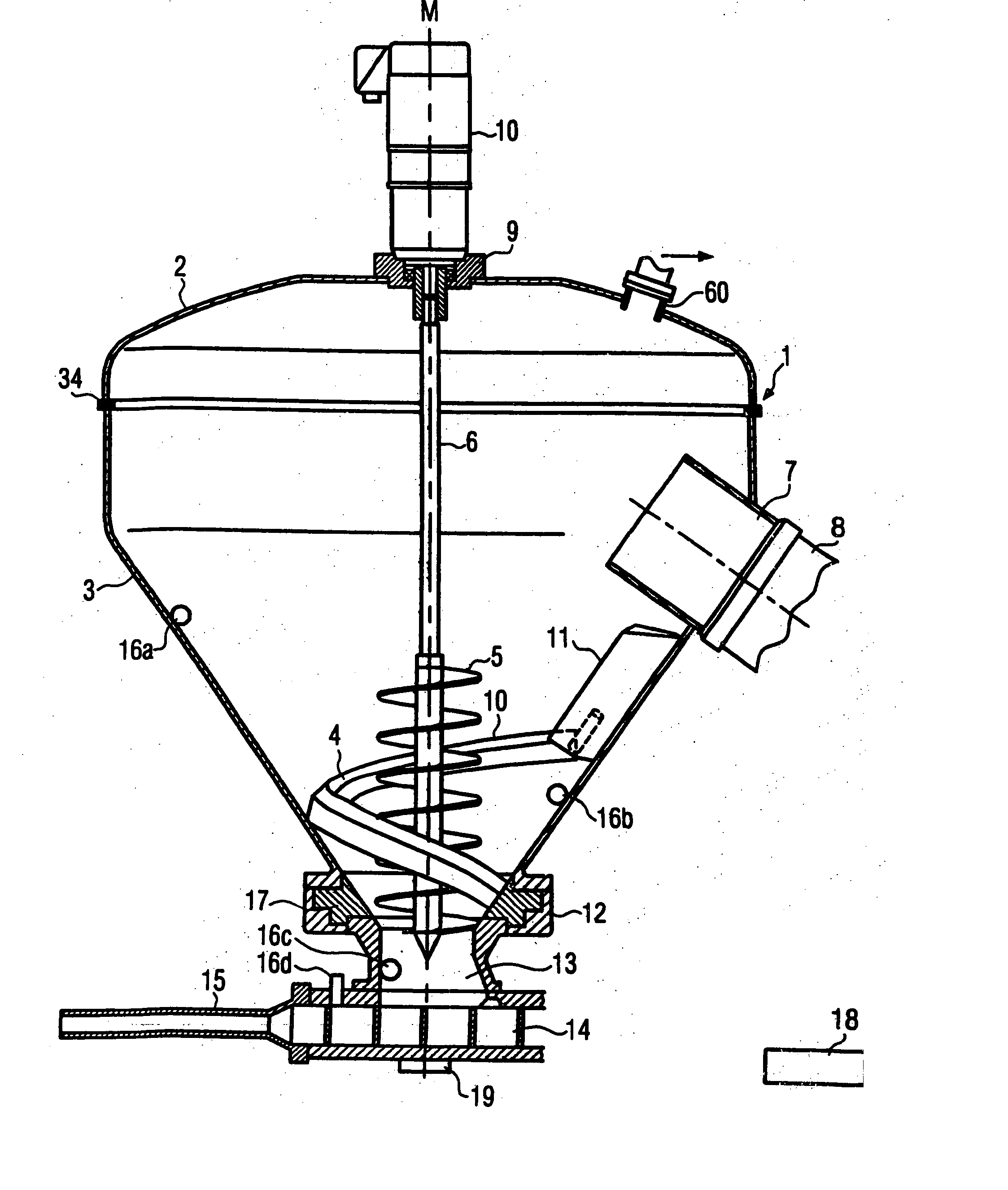
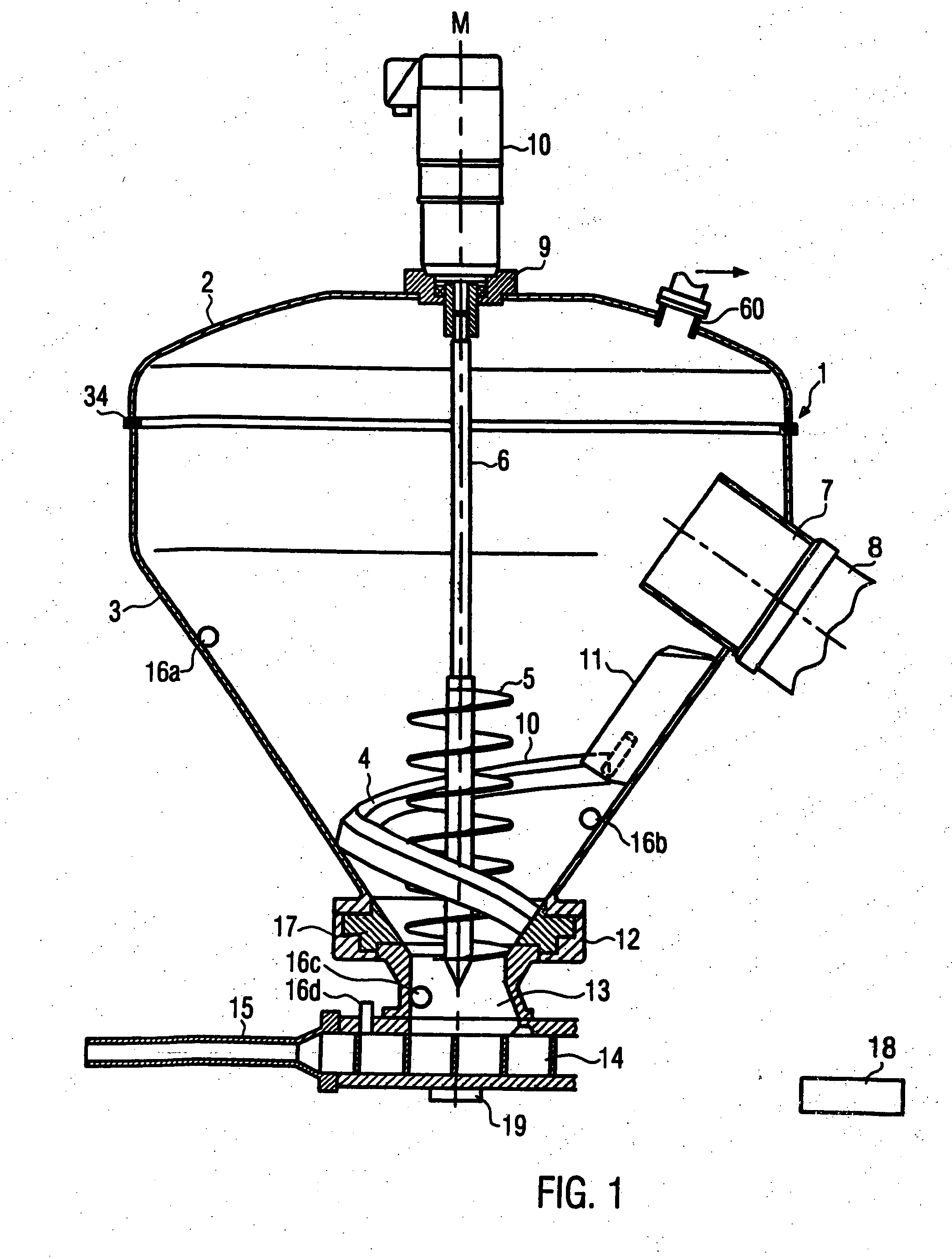
[0023]FIG. 1 shows an embodiment of a filling machine according to the disclosure. The filling machine according to the disclosure comprises a hopper 1, preferably a vacuum hopper 1, which comprises a lid 2 and a hopper section 3 which runs at least partly conically. The hopper section 3 and the lid 2 are connected together vacuum-tight via a seal 34, e.g, a sealing ring. The hopper 1 is in this embodiment a vacuum hopper in which a negative pressure can be produced. The vacuum hopper 1 comprises an inlet 7 for feeding a paste mass from a reservoir which is not illustrated via the feed tube 8. The hopper 1 also comprises at the lower end, i.e. at the end opposite the lid 2, an outlet region 13 for the paste mass. At the outlet region 13, a conveying mechanism 14 is arranged which conveys the paste mass from the hopper 1 into a filling tube 15. A vacuum pump 19, which is only illustrated schematically, is used to produce a negative pressure in the conveying mechanism or in the convey...


PUM


Abstract

A method and a filling machine for charging paste mass, in particular sausage meat, with a conveying mechanism 14 arranged at the lower end 3 of the hopper 1 and a feed device 4, 5 for feeding the paste mass from the hopper into the conveying mechanism. To facilitate the charging of the conveying mechanism from the hopper 1 continuously and completely with paste mass, and namely independent of the degree of evacuation and the filling level of the paste mass, the feed device comprises a combination of a feeder curve 4 and a screw conveyor 5 arranged within the feeder curve.

Description

CROSS-REFERENCE TO RELATED APPLICATION [0001] The present application claims the benefit of priority of European Patent Application No. 06004279.3 filed on Mar. 2, 2006. The entire text of the priority application is incorporated herein by reference in its entirety. FIELD OF THE DISCLOSURE [0002] The disclosure relates to a filling machine and a method of charging paste masses, in particular sausage meat. BACKGROUND OF THE DISCLOSURE [0003] The types of filling machine for charging paste mass, in which the paste mass from a hopper is introduced into a conveying mechanism, from where it is ejected into a filling tube in order to fill sausage casings with paste mass, are already known from the state of the art. [0004] Normally, during sausage production filling machines are used, the hoppers of which are open at the top. Here, the sausage meat in the hopper is fed by a circulating feeder curve to the center and to a certain extent downwards to the conveying mechanism, wherein a scrape...

Claims


Application Information

Patent Timeline
Patent Type & Authority Applications(United States)
IPC IPC(8): A22C11/00A22C11/08
CPCA22C11/08
Inventor MAILE, BERND
Owner ALBERT HANDTMANN MASCHFABRICK
Why Eureka
Try Eureka