

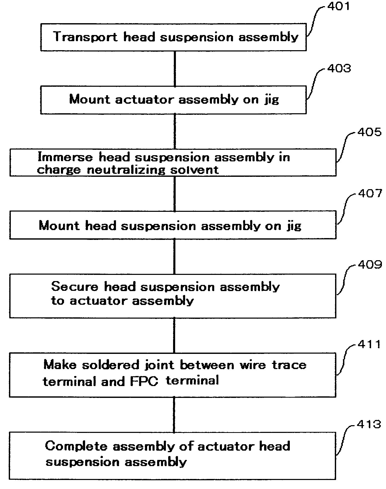
Method for assembling an actuator head suspension
a technology of actuator head and suspension assembly, which is applied in the direction of maintaining the head carrier alignment, protective measures for recording heads, magnetic recording, etc., can solve the problems that the ionizer or the ground panel is not good enough to sufficiently neutralize the charge, and achieves easy and reliably neutralization, high insulation resistance, and easy and reliably neutralizing the charge
- Summary
- Abstract
- Description
- Claims
- Application Information
AI Technical Summary
Benefits of technology
Problems solved by technology
Method used
Image

Examples
Embodiment Construction
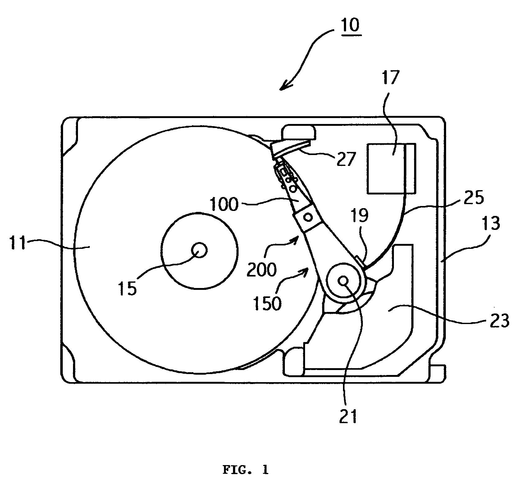
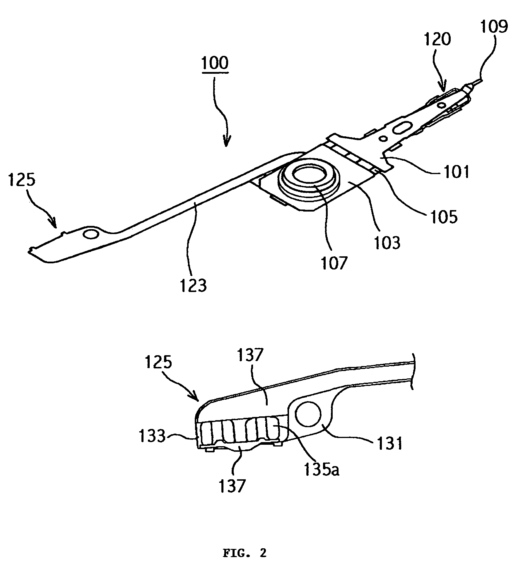
[0026]An exemplary embodiment of the present invention will be described with reference to the accompanying drawings. Similar reference numerals have been used throughout the entire specification to denote similar parts. FIG. 1 is a plan view showing the construction of a magnetic disk device 10 that uses an actuator head suspension assembly fabricated through an assembly process in accordance with the exemplary embodiment of the present invention. Parts mounted on a base 13 of the magnetic disk device 10 include the following: specifically, an actuator head suspension assembly 200, a magnetic disk 11, a ramp 27, and the like. The actuator head suspension assembly 200 pivots about a pivot shaft 21. The magnetic disk 11 spins about a spindle shaft 15. The ramp 27 achieves a load / unload type operation. The actuator head suspension assembly 200 includes an actuator assembly 150 and a head suspension assembly 100.
[0027]The head suspension assembly 100 is secured to an actuator arm of th...
PUM
| Property | Measurement | Unit |
|---|---|---|
| thickness | aaaaa | aaaaa |
| thickness | aaaaa | aaaaa |
| time | aaaaa | aaaaa |
Abstract
Description
Claims
Application Information