Vehicle steering control apparatus and method

a steering control and vehicle technology, applied in the direction of power steering steering, fluid steering, vehicle components, etc., can solve the problem of unnatural steering feel for the driver

Active Publication Date: 2007-09-20
NISSAN MOTOR CO LTD
View PDF12 Cites 26 Cited by
  • Summary
  • Abstract
  • Description
  • Claims
  • Application Information

AI Technical Summary

Benefits of technology

[0008]The present invention was conceived in view of the problem just described. One object is to provide a vehicle steering control apparatus that can accurately determine when the clutch has actually engaged regardless of variations in the clutch engagement time and smoothly shift to a steering wheel operation mode immediately after the clutch has actually engaged.

Problems solved by technology

Consequently, during the period from when the clutch actually engages until the prescribed amount of time elapses, the steering wheel will be connected directly to the steered wheels through the clutch and a reaction force will develop which holds the steering wheel in place, resulting in an unnatural steering feel for the driver.

Method used


Image

  • Vehicle steering control apparatus and method
  • Vehicle steering control apparatus and method
  • Vehicle steering control apparatus and method

Examples


second embodiment

[0098]A second embodiment will now be described in which the steering holding control of the first embodiment is replaced with a slow steering control as the clutch engagement transitional steering control.

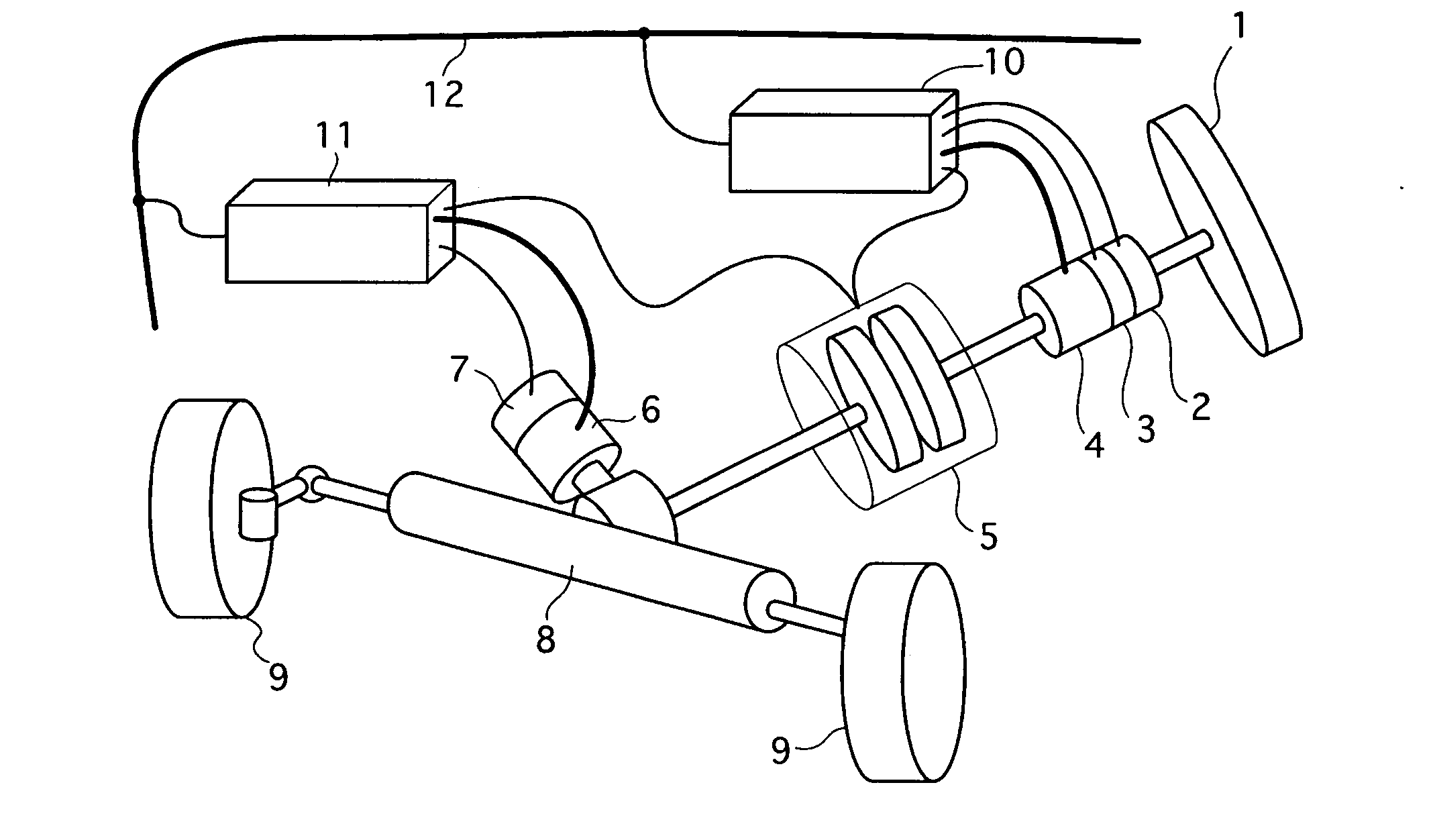
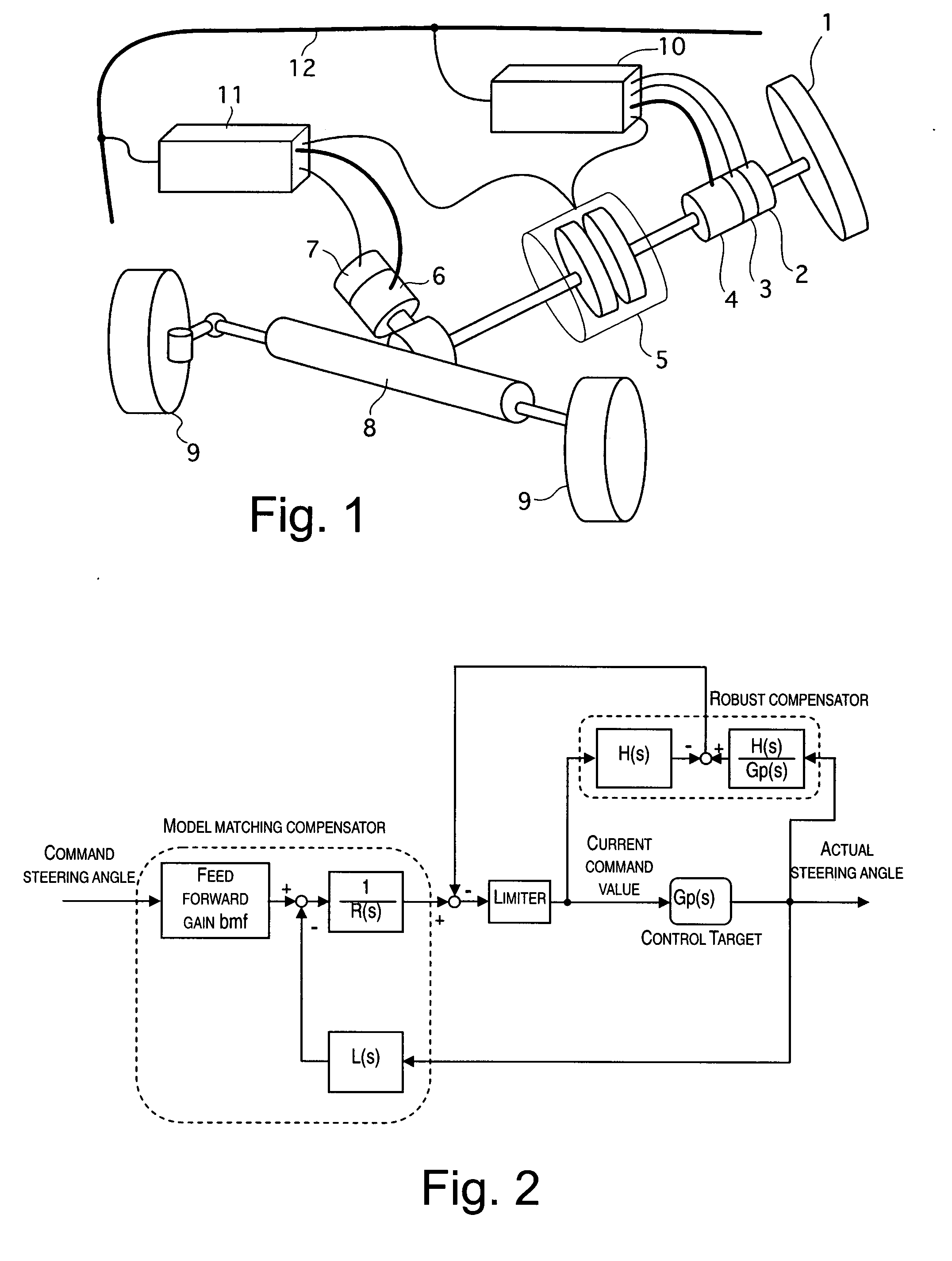
[0099]Otherwise, the constituent features of the second embodiment are the same as those of the first embodiment shown in FIGS. 1 to 2 and explanations and drawings thereof are omitted for the sake of brevity.

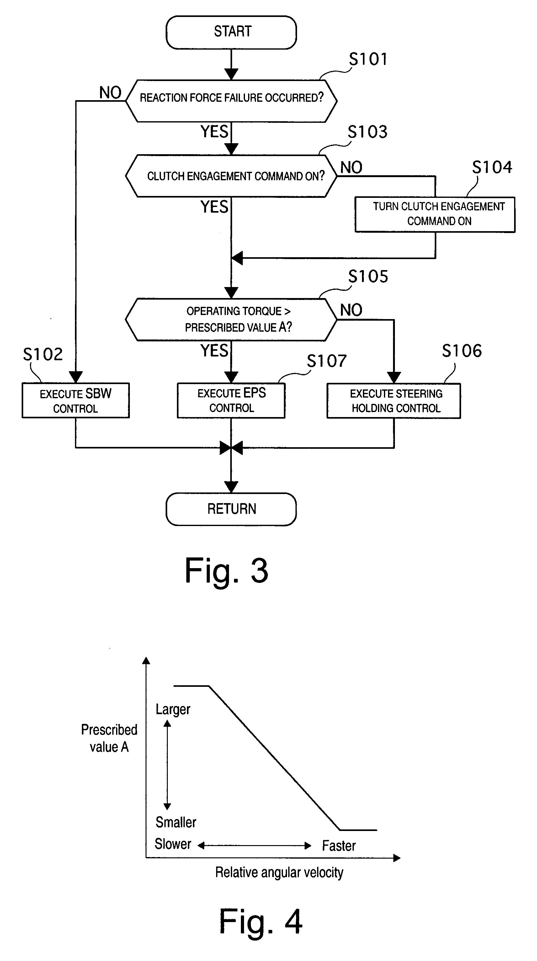
[0100]FIG. 9(a) is a flowchart showing control processing executed by the reaction force controller 10 and the steering controller 11 of the second embodiment in order to switch the control mode when a reaction force component failure (e.g., reaction force failure) occurs. Each step of the flowchart will now be explained. This processing sequence is executed by the controllers 10 and 11 once each time the SBW control cycle time elapses (e.g., every 5 msec). Steps S201 to S205 and step S207 are the same as steps S101 to S105 and S107, respectively, of the flowchart shown in FI...

third embodiment

[0128]A third embodiment will now be described in which the apparatus is configured to switch from a SBW control to an EPS control with the clutch connected when the voltage of a power source declines.

[0129]Otherwise, the constituent features of the third embodiment are the same as those of the first embodiment shown in FIGS. 1 to 2 and explanations and drawings thereof are omitted for the sake of brevity.

[0130]FIG. 12 is a flowchart showing control processing executed by the reaction force controller 10 and the steering controller 11 of the third embodiment in order to switch the control mode when a the voltage of the power source declines. Each step of the flowchart will now be explained. This processing sequence is executed by the controllers 10 and 11 once each time the SBW control cycle time elapses (e.g., every 5 msec). The processing of steps S302 to S307 is the same as in steps S102 to S107, respectively, of the flowchart 3 and explanations there of are omitted for the sake ...

fourth embodiment

[0163]The constituent features of the fourth embodiment are the same as those of the first embodiment shown in FIGS. 1 to 2 and explanations and drawings thereof are omitted for the sake of brevity.

[0164]In the first embodiment, after the engagement command is issued to the clutch 5, the clutch engagement determining section determines that the clutch 5 has entered an engaged state when the operating torque detected by the torque sensor 3 exceeds a prescribed value A (clutch engagement determination threshold value). However, it is also acceptable to determine that the clutch has engaged when a derivative of the operating torque (rate of change of the operating torque) exceeds a clutch engagement determination threshold value, as shown in FIG. 18 (step S405).

[0165]Steps S401 to S404 and steps S406 and S407 are the same as steps S101 to S104 and steps S106 and S107, respectively, of the flowchart 3 and explanations there of are omitted for the sake of brevity.

[0166]In this patent spe...


PUM


Abstract

A vehicle steering control apparatus includes a steering wheel to be operated by a driver, a steering mechanism for turning the front wheels in accordance with an operating torque of the steering wheel, and a clutch for mechanically connecting the steering wheel to the steering mechanism. A clutch engagement command issuing section is provided for issuing an engagement command to the clutch when the clutch is disengaged and a condition for engaging the clutch is satisfied. A clutch engagement determining section is provided for determining that the clutch is in an engaged state when an increase in torque is detected at the steering wheel after the engagement command has been issued to the clutch.

Description

CROSS-REFERENCE TO RELATED APPLICATIONS[0001]This application claims priority to Japanese Patent Application No. 2006-057271, filed on Mar. 3, 2006. The entire disclosure of Japanese Patent Application No. 2006-057271 is hereby incorporated herein by reference.BACKGROUND OF THE INVENTION[0002]1. Field of the Invention[0003]The present invention generally relates a vehicle steering control apparatus for a steer-by-wire system provided with a clutch for mechanically connecting and disconnecting a driver operating unit configured to be operated by a driver and a steering unit configured to steer a steered wheel to and from each other.[0004]2. Background Information[0005]In conventional steer-by-wire (SBW) systems in which the steering wheel and the steering mechanism of the front wheels are mechanically separated from each other, a clutch is provided as a backup mechanism for mechanically connecting the steering wheel and the steering mechanism. When a problem (failure) occurs in a por...

Claims


Application Information

Patent Timeline
Patent Type & Authority Applications(United States)
IPC IPC(8): B62D5/00
CPCB62D5/001B62D5/0481B62D5/0478B62D5/003
Inventor TSUTSUMI, JUNJIKASAHARA, TOSHIAKI
Owner NISSAN MOTOR CO LTD
Why Eureka
Try Eureka