

Self-propelled wheel for bicycles and similar vehicles
a self-propelled wheel and bicycle technology, applied in the direction of steering devices, frictional roller based transmissions, cycle equipments, etc., can solve the problems of time-consuming installation and removal of the propulsion assistor, affecting the operation of the steering device, and changing the handling characteristics and effective size of the vehicl
- Summary
- Abstract
- Description
- Claims
- Application Information
AI Technical Summary
Problems solved by technology
Method used
Image

Examples
Embodiment Construction
[0023] To illustrate the invention and the various forms that it may take, following is a description of the preferred version of the invention, and several exemplary variations, which will be described with reference to the accompanying drawings.
Preferred Version of the Invention (FIGS. 1-4)
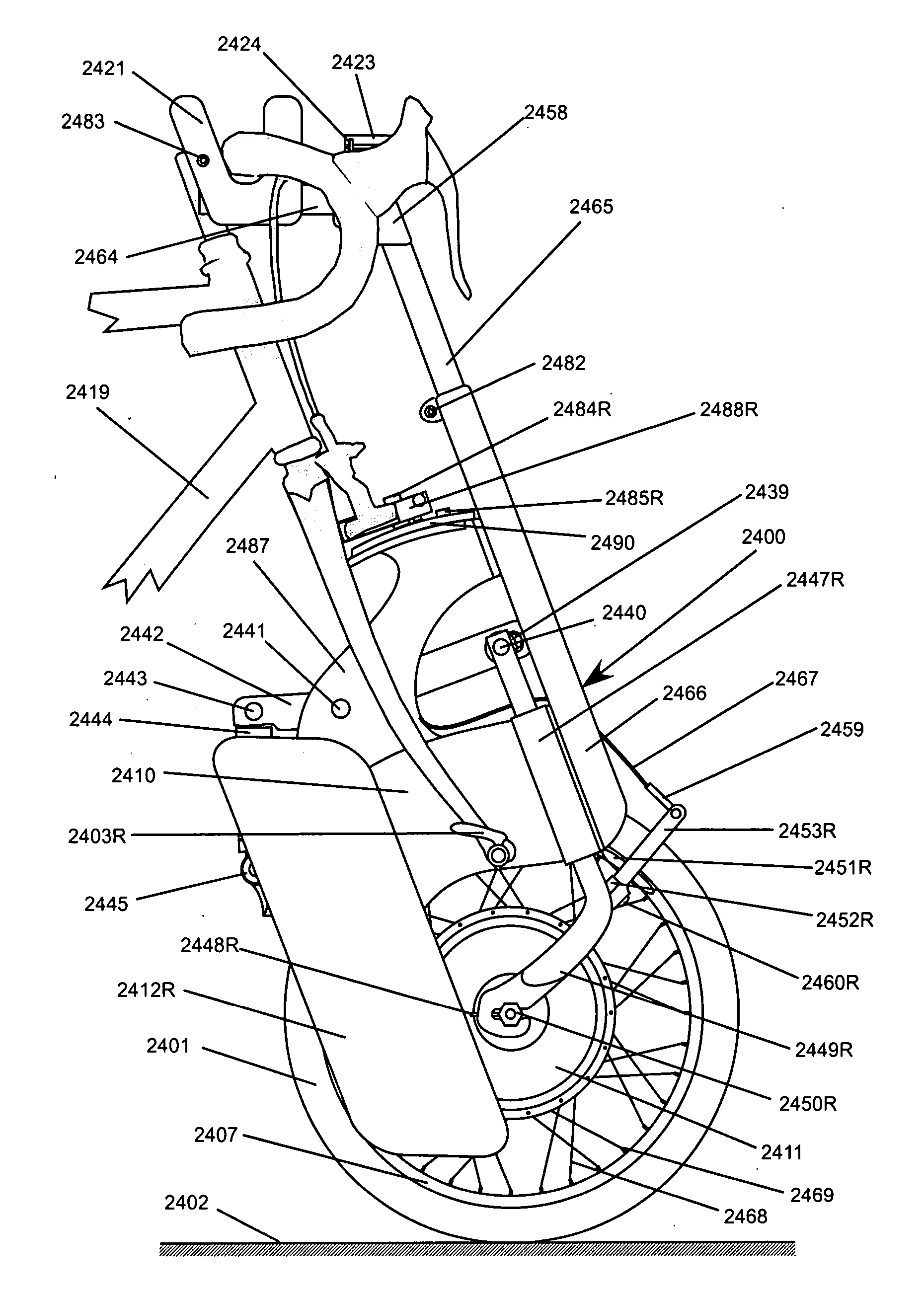
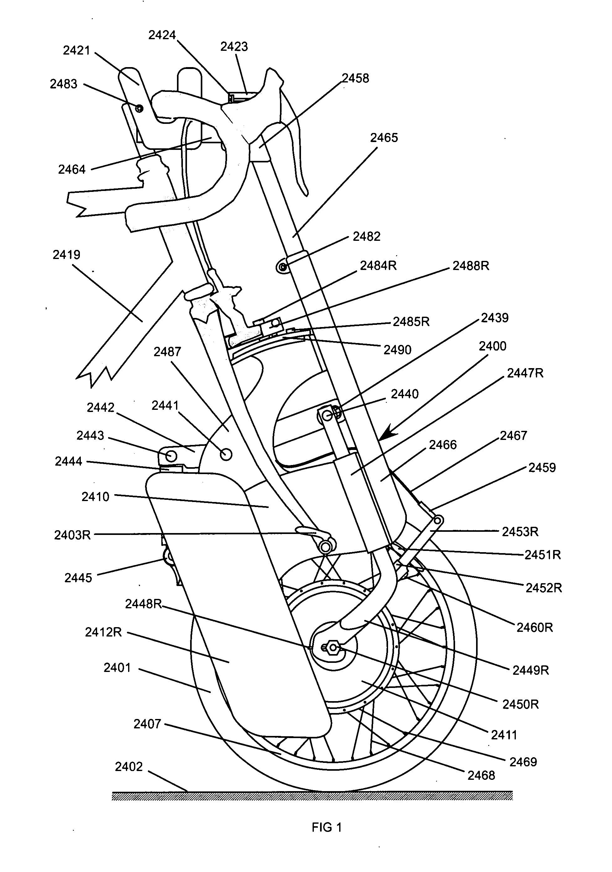
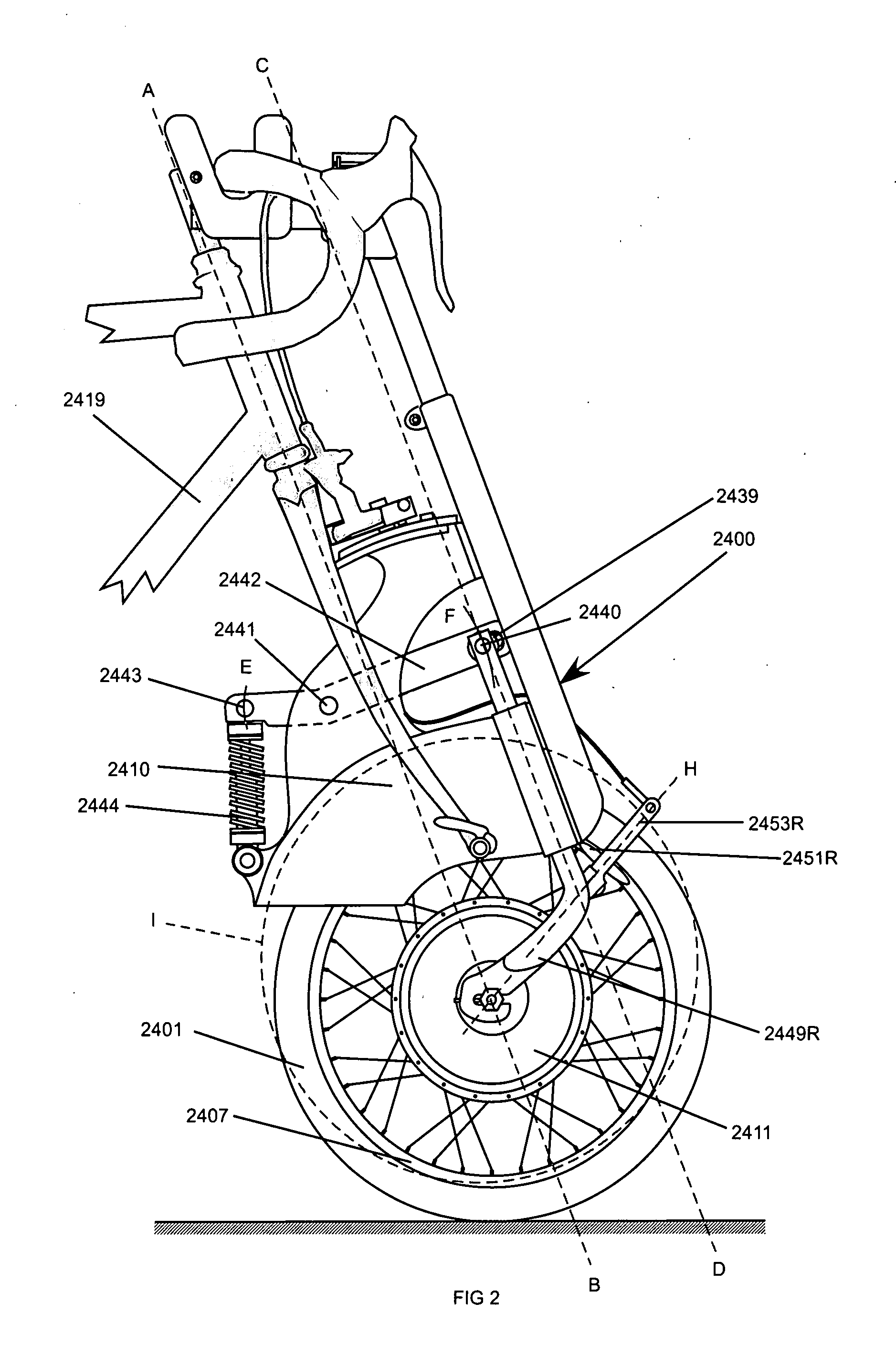
[0024] This preferred version comprises a wheel propulsion assembly. The wheel propulsion assembly comprises a suspension assembly, a motor driven rotatable wheel with a wheel axle located concentrically therein, a motor to drive said rotatable wheel, and a restraining member for preventing the wheel propulsion assembly from rotating about the fork dropouts. The suspension assembly creates a smoother ride, improving rider comfort and wheel propulsion assembly durability.
[0025]FIG. 1 shows a view of the right side of a wheel propulsion assembly 2400 specifically configured for use with a bicycle 2419. The wheel propulsion assembly 2400 includes a tire 2401, which contacts a pavement 2402 duri...
PUM
 Abstract
Description
Claims
Application Information