Semi-disposable pre-conditioned air supply hose conduit and connectors for attaching end portions of the same

a technology of pre-conditioned air supply and hose conduit, which is applied in the direction of hose connection, pipe-joint, coupling, etc., can solve the problems of only being used, the fastening means do not truly address, etc., and achieve the effect of convenient and convenient folding, unfolding or disposed, readily and easily deployed, stowed or stored

Active Publication Date: 2007-09-20
ILLINOIS TOOL WORKS INC
View PDF17 Cites 1 Cited by
  • Summary
  • Abstract
  • Description
  • Claims
  • Application Information

AI Technical Summary

Benefits of technology

[0007] The foregoing and other objectives are achieved in accordance with the teachings and principles of the present invention through the provision of a new and improved tubular fluid conduit which is especially adapted for use in supplying pre-conditioned air to an aircraft while, for example, the aircraft is located upon the ground and being serviced, during which time the aircraft is unable to generate its own supply of conditioned air for the crew and passengers, wherein the tubular conduit may be fabricated, in accordance with a first embodiment, as a thermoplastic extrusion which has a constant diameter dimension that may be cut or separated to a predeterminedly desired length dimension, or which may be fabricated, in accordance with a second embodiment, as a thermoplastic extrusion which effectively has repetitive length sections which have both relatively large diameter and relatively small diameter sections. Both embodiment tubular fluid conduits may be cut or separated to predeterminedly desired length dimensions.
[0008] In the first instance, while the diametrical extent of the tubular fluid conduit extrusion is constant, the opposite end portions of the tubular fluid conduit extrusion may be respectively secured to fluid conduits, having different, relatively large and relatively small diametrical dimensions, by attaching one end portion of the tubular conduit extrusion to the relatively large diameter fluid conduit, while spirally gathering or folding the other end portion of the tubular conduit extrusion around the longitudinal axis thereof so as to be attached to the relatively small diameter fluid conduit. In the second instance, each repetitive length section has a relatively large diameter and relatively small diameter end portion formed or incorporated therein whereby, when a particular section of the extrusion is separated from another section, at the interface defined between one of the relatively large diameter portions and one of the relatively small diameter portions, so as to define a tubular conduit of a predetermined length, the relatively large end portion of the tubular conduit can be readily connected to a relatively large diameter fluid conduit while the oppositely disposed relatively small portion of the tubular conduit can be readily connected to a relatively small diameter fluid conduit. Since the tubular fluid conduit is fabricated as an extrusion in a flattened state, the tubular fluid conduit may be readily and easily folded, unfolded, or disposed upon a reel, in its flattened state, so as to be capable of being readily and easily deployed, stowed, or stored.

Problems solved by technology

It can be further appreciated, however, that while such fabrication techniques are quite satisfactory from the viewpoint of initially fabricating, forming, or erecting the tubular fluid conduit, such fastening means do not truly address the additionally important issues of providing the overall tubular fluid conduit with means for effectively enabling the relatively easy and rapid deployment of the tubular fluid conduit, the relatively easy and rapid stowing of the tubular fluid conduit, or the capability of the tubular fluid conduit to be stored in a relatively compact mode and space.
In addition, it is also noted that such conventional, PRIOR ART tubular fluid conduits have a predetermined, constant diametrical extent, and therefore, such tubular fluid conduits can only be utilized in connection with fluid flow systems which employ tubular fluid conduits having a predetermined constant diametrical extent.

Method used


Image

  • Semi-disposable pre-conditioned air supply hose conduit and connectors for attaching end portions of the same
  • Semi-disposable pre-conditioned air supply hose conduit and connectors for attaching end portions of the same

Examples


Embodiment Construction

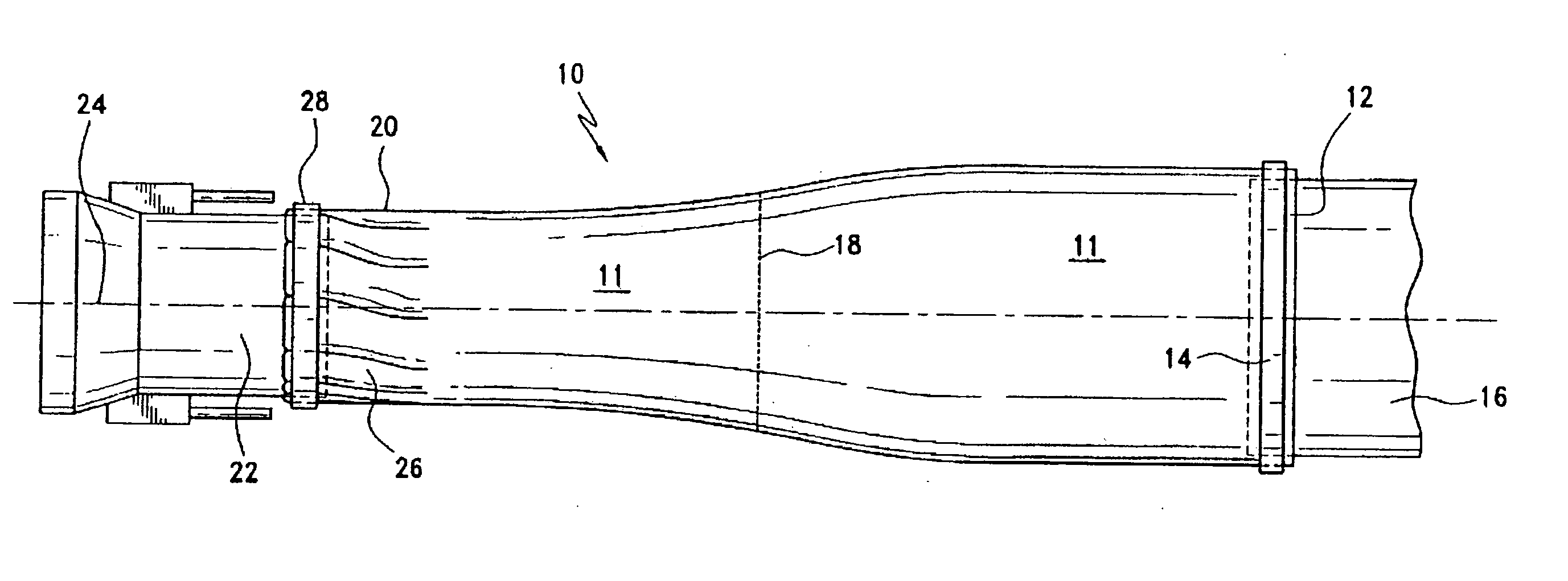
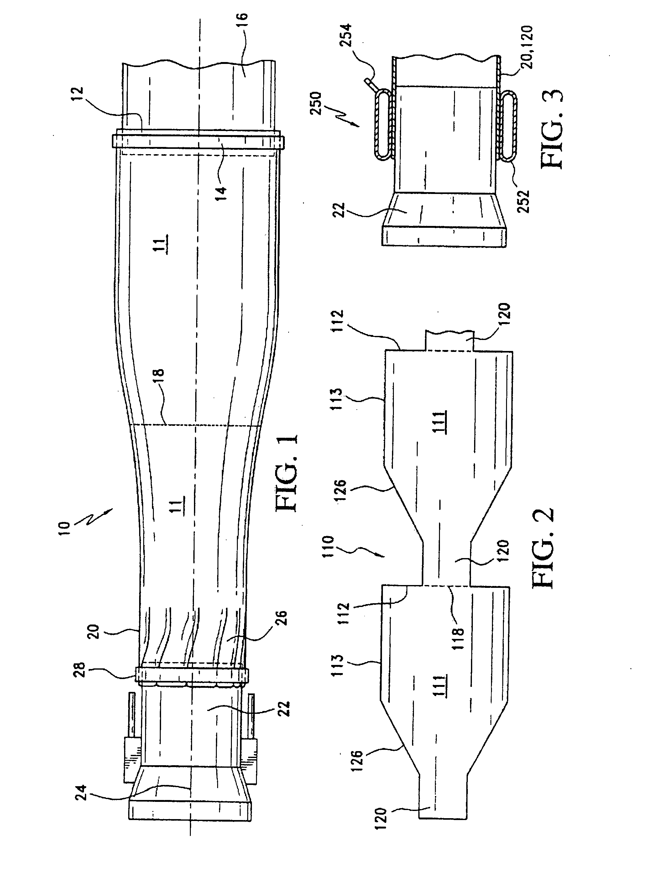
[0013] Referring now to the drawings, and more particularly to FIG. 1 thereof, a first embodiment of a new and improved tubular fluid conduit, especially adapted for supplying pre-conditioned air to aircraft while the aircraft is upon the ground and being serviced, and is therefore incapable of providing its own pre-conditioned air to the passengers and crew, is disclosed and is generally indicated by the reference character 10. More particularly, the new and improved tubular fluid conduit 10 is fabricated as a continuous tubular extrusion from a suitable thermoplastic material, such as, for example, polyethylene or polyvinyl, and may have a thickness dimension which may be within the range of, for example, five to seven mils (0.005-0.007″). The tubular fluid conduit 10 is extruded in the form of a flattened tubular member which may be folded, or coiled upon a reel, for easy stowage and storage purposes, and in accordance with the principles and teachings of the first embodiment of ...


PUM

PropertyMeasurementUnit
thicknessaaaaaaaaaa
distancesaaaaaaaaaa
diameteraaaaaaaaaa

Abstract

A tubular fluid conduit which is especially adapted for use in supplying pre-conditioned air to an aircraft being serviced, wherein the tubular conduit may be fabricated as a thermoplastic extrusion having a constant diameter dimension, whereby a first end portion may be fluidically connected to a large diameter supply conduit while a second end portion may be fluidically connected to a small diameter use conduit as a result of spiral wrapping the second end portion around the use conduit. Alternatively, the tubular conduit may be fabricated as a thermoplastic extrusion having repetitive sections with each section comprising relatively large diameter and relatively small diameter portions.

Description

CROSS REFERENCE TO RELATED APPLICATION [0001] This application claims priority to U.S. Provisional Application No. 60 / 781,843, filed on Mar. 13, 2006, which is hereby incorporated by reference.FIELD OF THE INVENTION [0002] The present invention relates generally to tubular fluid conduits, and more particularly to a new and improved tubular fluid conduit which is especially adapted for use in supplying pre-conditioned air to an aircraft while, for example, the aircraft is located upon the ground and being serviced, during which time the aircraft is unable to generate its own supply of conditioned air for the crew and passengers, wherein the tubular conduit may be fabricated, in accordance with a first embodiment, as a thermoplastic extrusion which has a constant diametrical dimension, or which may be fabricated, in accordance with a second embodiment, as a thermoplastic extrusion which effectively has repetitive length sections wherein each one of the repetitive length sections has a...

Claims


Application Information

Patent Timeline
Patent Type & Authority Applications(United States)
IPC IPC(8): F16L37/00
CPCF16L47/265F16L25/14F16L47/26
Inventor GOSIS, ANATOLYKOIZUMI, SCOTTKOCH, FOLKERT
Owner ILLINOIS TOOL WORKS INC
Why Eureka
Try Eureka