
Microphone connector module

Inactive Publication Date: 2007-09-20
CHENG UEI PRECISION IND CO LTD
View PDF4 Cites 2 Cited by
  • Summary
  • Abstract
  • Description
  • Claims
  • Application Information

AI Technical Summary

Benefits of technology

[0007] Accordingly, an object of the present invention is to provide a microphone connector module, comprising a microphone having a contacting face and a receiving face, a plurality of terminals, a body and a casing. The bottom portion of the terminal is bent to form a first elastic portion for pressing the contacting face of the microphone. The top portion of the terminal is bent to form a second elastic portion for pressing an external PCB. The body defines a cylindrical cavity to receive the microphone. The casing further includes a basic portion and a front portion stretching forward from the basic portion. The basic portion defines a housing for accommodating the microphone connector module. The front portion defines a voice channel communicating with the housing of the basic portion for allowing the external voice to reach the receiving face of the microphone. The voice channel is approximately perpendicular to the housing of the basic portion. While coming into the voice channel, the acoustic wave of the external voice reaches approximately to the receiving face of the microphone. This structure avoids the influence caused by the receiving of the acoustic waves of different frequency at the same time and enhances the receiving effect of the microphone.

Problems solved by technology

While more than one acoustic wave reach the receiving face of the microphone at the same time, the acoustic waves of different frequency may cause the acoustic wave receiving equipment to shake at different frequency, which may influence the shaking of the acoustic wave receiving equipment and further influence the transformation of the voice into electric signals.

Method used


Image

  • Microphone connector module
  • Microphone connector module
  • Microphone connector module

Examples


Embodiment Construction

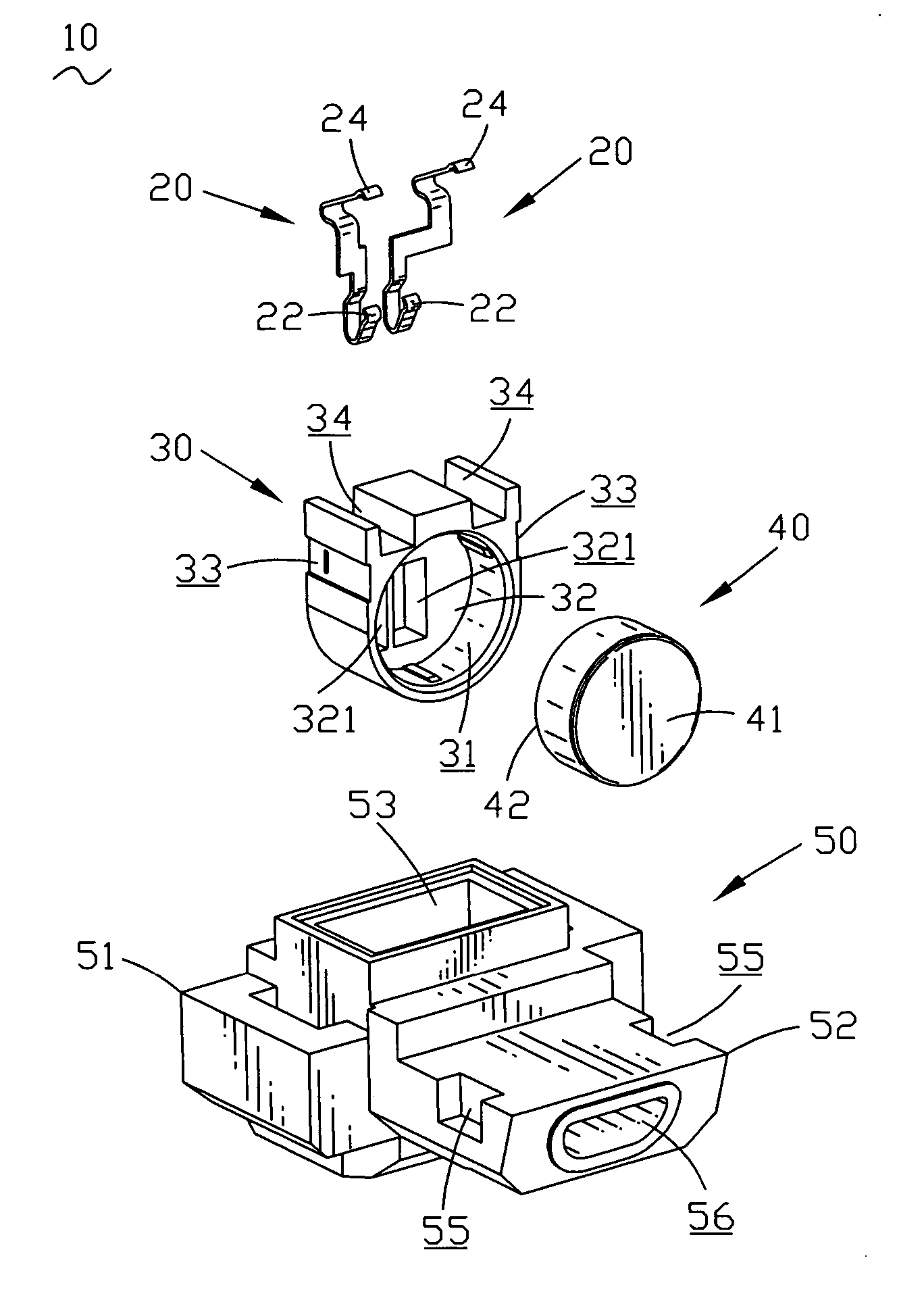
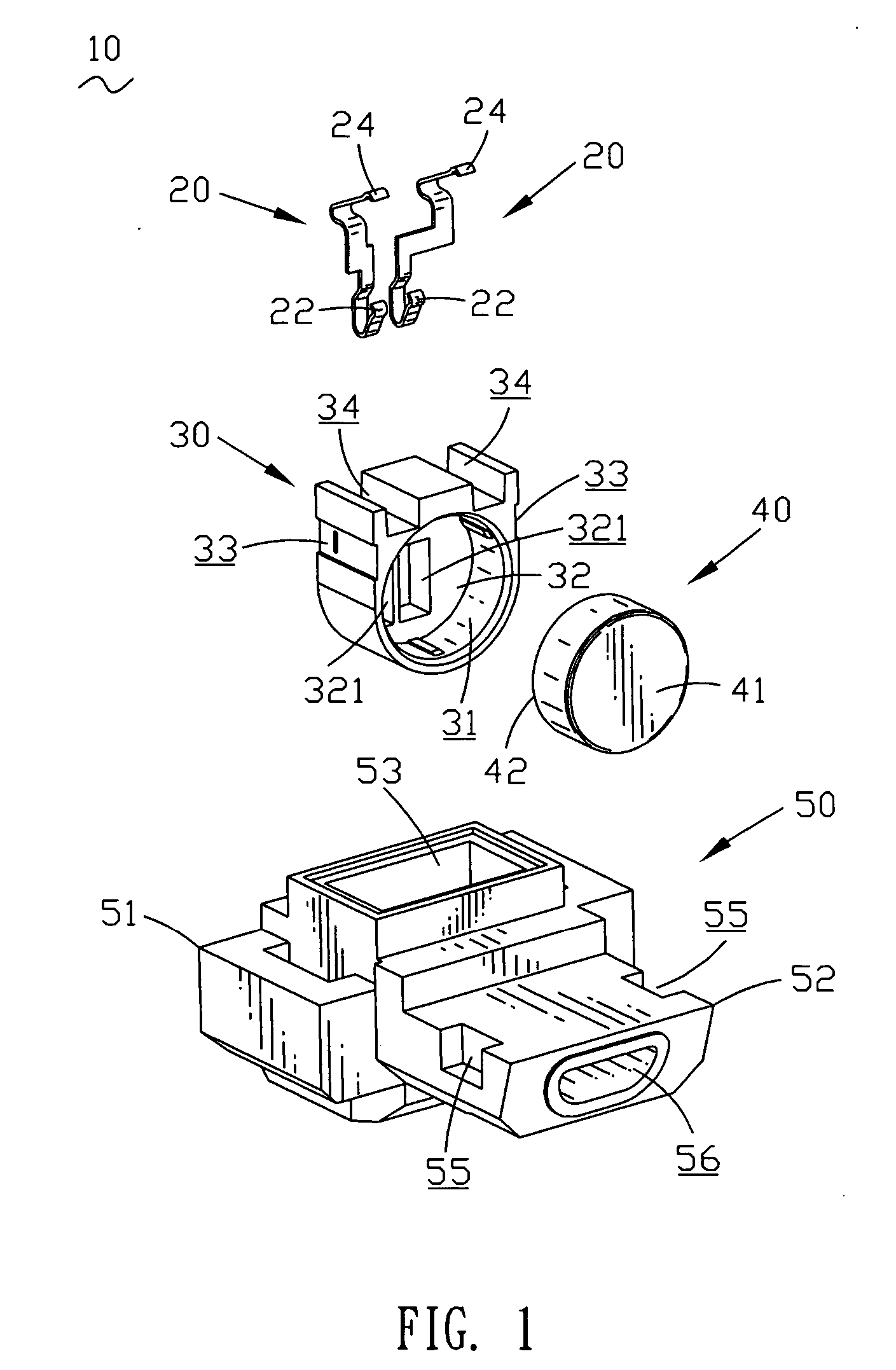
[0013] Referring to FIG. 1, an embodiment of a microphone connector module 10 in accordance with the present invention is shown. The microphone connector module 10 comprises a pair of terminals 20, a body 30 receiving the terminals 20, a microphone 40 received in the body 30, and a casing 50 receiving the body 30.

[0014] As shown in FIG. 1, the microphone 40 defines a receiving face 41 and a contacting face 42 opposite to the receiving face 41.

[0015] The terminals 20 are received and fixed in the body 30. The bottom portion of the terminal 20 is bent to form a first elastic portion 22 for pressing the contacting face 42 of the microphone 40. The top portion of the terminal 20 is bent to form a second elastic portion 24 for pressing an external printed circuit board (PCB, not shown).

[0016] The body 30 defines a cylindrical cavity 31 for receiving the microphone 40. The back portion of the body 30 defines a back wall 32 as a bottom of the cylindrical cavity 31. The back portion of t...


PUM


Abstract

A microphone connector module includes a microphone with a receiving face and a contacting face, a body defining a cavity to receive the microphone, a pair of terminals fixed in the body and connecting with the microphone and an external printed circuit board and a casing including a basic portion and a front portion. The basic portion of the casing defines a housing to receive the body. The front portion of the casing defines a voice channel approximately perpendicularly communicating with the housing of the basic portion. The receiving face of the microphone approximately perpendicularly faces to the voice channel and only receives the acoustic waves of single frequency at a time, which avoids the influence of a mixed transformation of the acoustic waves of different frequency to electric signals and enhances the receiving effect of the microphone.

Description

BACKGROUND OF THE INVENTION [0001] 1. Field of the Invention [0002] The present invention relates to a microphone connector module, and particular relates to a microphone connector module with voice channel. [0003] 2. The Related Art [0004] Microphone connector modules are widely used, for example, in mobile telecommunication equipment, such as portable telephones. The connectors are permanently incorporated so that the transformation of the data can be set up with an external information-processing unit, such as a microcomputer. The connectors can transfer electrical power from a source of electrical power to the equipment coupled to the external unit via the appropriate connector. Such a connector also allows an electrical connection to be made between a microphone in the mobile telecommunication equipment and a printed circuit board (PCB) of the mobile telecommunication equipment. [0005] U.S. Pat. No. 6,654,464 issued Nov. 25, 2003 describes a microphone connector module, which i...

Claims


Application Information

Patent Timeline
IPC IPC(8): H04R3/00H04R1/02
CPCH01R13/24H01R13/6608H01R12/714H04R1/083H01R2201/06
Inventor HO, HSIN-TSUNG
Owner CHENG UEI PRECISION IND CO LTD
Features
  • Generate Ideas
  • Intellectual Property
  • Life Sciences
  • Materials
  • Tech Scout
  • Unparalleled Data Quality
  • Higher Quality Content
  • 60% Fewer Hallucinations
Learn More