Solar energy lane marking system

Inactive Publication Date: 2007-09-20
YANG FUFU
View PDF23 Cites 8 Cited by
  • Summary
  • Abstract
  • Description
  • Claims
  • Application Information

AI Technical Summary

Benefits of technology

[0008] A main object of the present invention is to provide a solar energy lane marking system which is capable of centrally collecting solar energy for use by a predetermined section of lane marker

Problems solved by technology

There are plenty disadvantages in associated with it.
In many occasions, drivers are unable to see the painted lines clearly so as to cause many accidents.
This kind of lane markers are said to have short life-span, require frequent replacement, and therefore involve expensive maintenance costs.
Despite relieving some deep-seated problems for conventional lane makers, this type of solar energy lane markers system has the disadvantages that the solar energy collection board usually cannot collect sufficient amount of solar energy for use by the respective lane markers.
Moreover, since the solar energy collection board is located near the lane markers, when there is no sunlight, the illumination unit would have insufficient power to operate so that the lanes cannot be clearly divided.
Obviously, this can lead to disastrous consequences.
Furthermore, even if the solar battery is fully charged, it can only be continuously utilized for up to around twenty hours.
Limited life-span: the solar battery usually has very limited life-span so th

Method used


Image

  • Solar energy lane marking system
  • Solar energy lane marking system
  • Solar energy lane marking system

Examples


Example

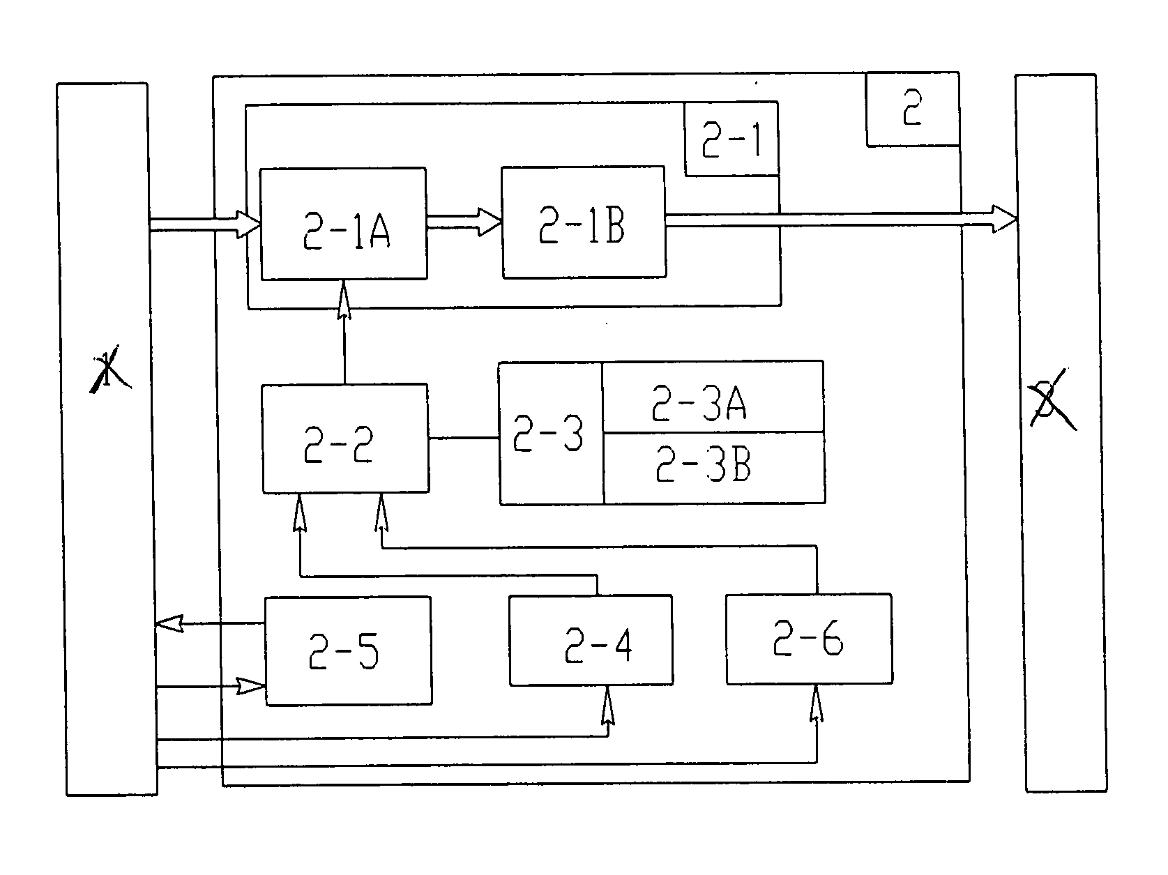
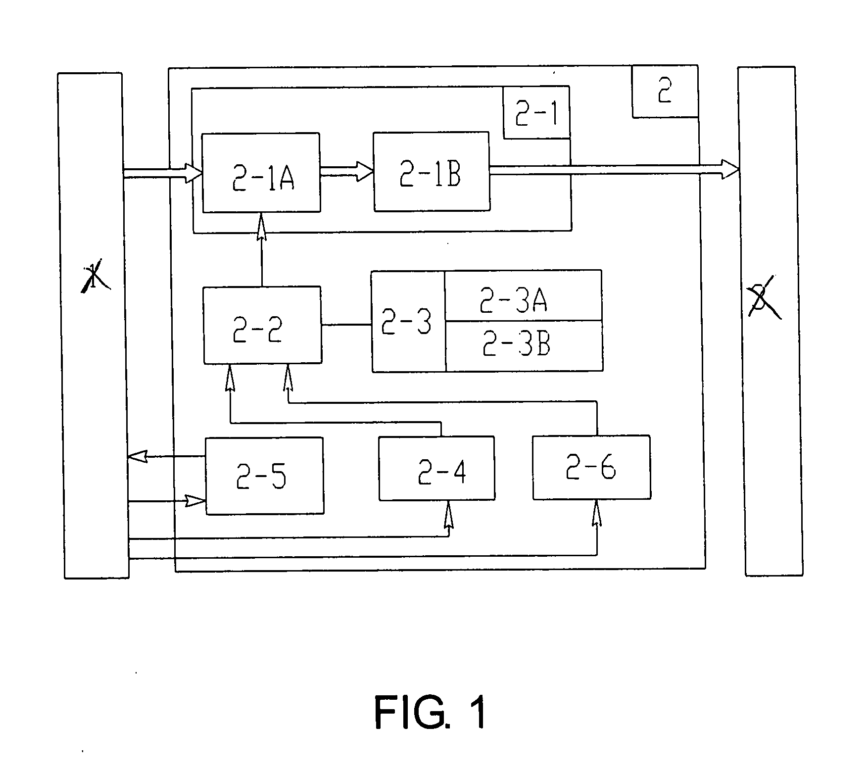
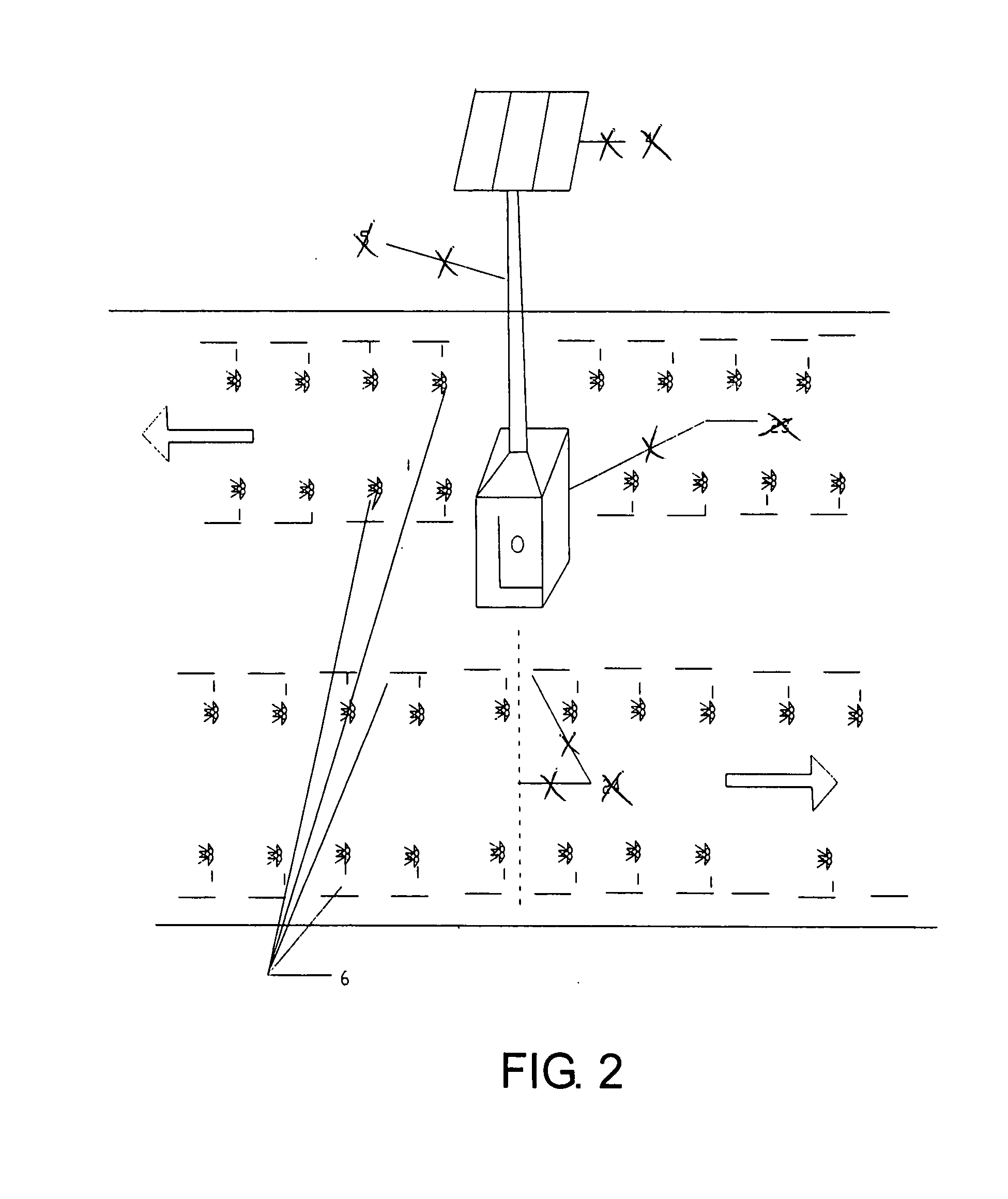
[0024] Referring to FIG. 1 to FIG. 5 of the drawings, a solar energy lane marking system for a road surface having at least a traffic lane according to a preferred embodiment of the present invention is illustrated, in which the solar energy lane marking system comprises at least one set of lane markers, and at least a solar energy collection arrangement.

[0025] The set of lane markers 10 is for spacedly providing on the road surface 70 to define the traffic lane, wherein each of the lane markers 10 comprises an illuminator 3 used for lane illumination.

[0026] The solar energy collection arrangement is for controlling the set of lane markers 10 in centralized manner so as to ensure sufficient and consistent illumination of the illuminators 3. The solar energy collection arrangement comprises a solar energy collector, an energy storage, and a central processing circuitry 2.

[0027] The solar energy collector, which is arranged for positioning away from the traffic lane, comprises a so...


PUM


Abstract

A solar energy lane marking system for a road surface having at least a traffic lane includes a set of lane markers, and a solar energy collection arrangement. The lane markers are for spacedly providing on the road surface to define the traffic lane, wherein each of the lane markers includes an illuminator for lane illumination. The solar energy collection arrangement is for controlling the set of lane markers in centralized manner to ensure sufficient and consistent illumination of the illuminators, and includes a solar energy collector for collecting solar energy, an energy storage, and a central processing circuitry. The central processing circuitry, which is electrically connecting the energy storage with the illuminators of the lane markers, operatively controls the illuminators of the lane markers as an illuminable road divider for identifying the traffic lane in case of low visibility of the traffic lane.

Description

BACKGROUND OF THE PRESENT INVENTION [0001] 1. Field of Invention [0002] The present invention relates to a lane marking system, and more particularly to a solar energy lane marking system which is capable of centrally collecting solar energy for use by a predetermined section of lane markers so as to ensure sufficient and consistent illumination of the lane markers. [0003] 2. Description of Related Arts [0004] Conventionally, lanes on a road are divided by painted lines for drivers to recognize. There are plenty disadvantages in associated with it. In many occasions, drivers are unable to see the painted lines clearly so as to cause many accidents. As a result, conventional lane markers have been developed for replacing traditional painted lines. In general, these conventional lane markers contain reflective materials which are capable of providing reflective illumination when they are exposed to the light emitted from vehicles' headlights. Therefore, these conventional lane markers...

Claims


Application Information

Patent Timeline
IPC IPC(8): E01F9/08
CPCE01F9/085E01F9/582
Inventor YANG, FUFU
Owner YANG FUFU
Why Eureka
Try Eureka