Pneumatic tool with pressure-stabilizing cylinder

a technology of pressure stabilizing cylinder and pneumatic tool, which is applied in the direction of machines/engines, rotary/oscillating piston pump components, liquid fuel engines, etc., can solve the problems of low cost of cylinder set, low torque for tightening fasteners, and high torque for slackening fasteners, etc., to ensure the integrity of fasteners, small torque, and quick slackening

Inactive Publication Date: 2007-09-20
PNEUTECH MANUFACTUER
View PDF21 Cites 4 Cited by
  • Summary
  • Abstract
  • Description
  • Claims
  • Application Information

AI Technical Summary

Benefits of technology

[0010] An advantage of the pneumatic tool of the present invention is to guarantee the integrity of a fastener by providing a small torque in the tightening mode and quickly slacken the fastener by providing a large torque in the slackening mode.

Problems solved by technology

The switch is however an instable design and may fail to provide stable torque because of excessive tolerance in the fabrication thereof or excessively high pressure of the air.
Furthermore, the cost of the cylinder set is low.
There is however a trend toward a low torque for tightening fasteners and a high torque for slackening such fasteners.

Method used


Image

  • Pneumatic tool with pressure-stabilizing cylinder
  • Pneumatic tool with pressure-stabilizing cylinder
  • Pneumatic tool with pressure-stabilizing cylinder

Examples


Embodiment Construction

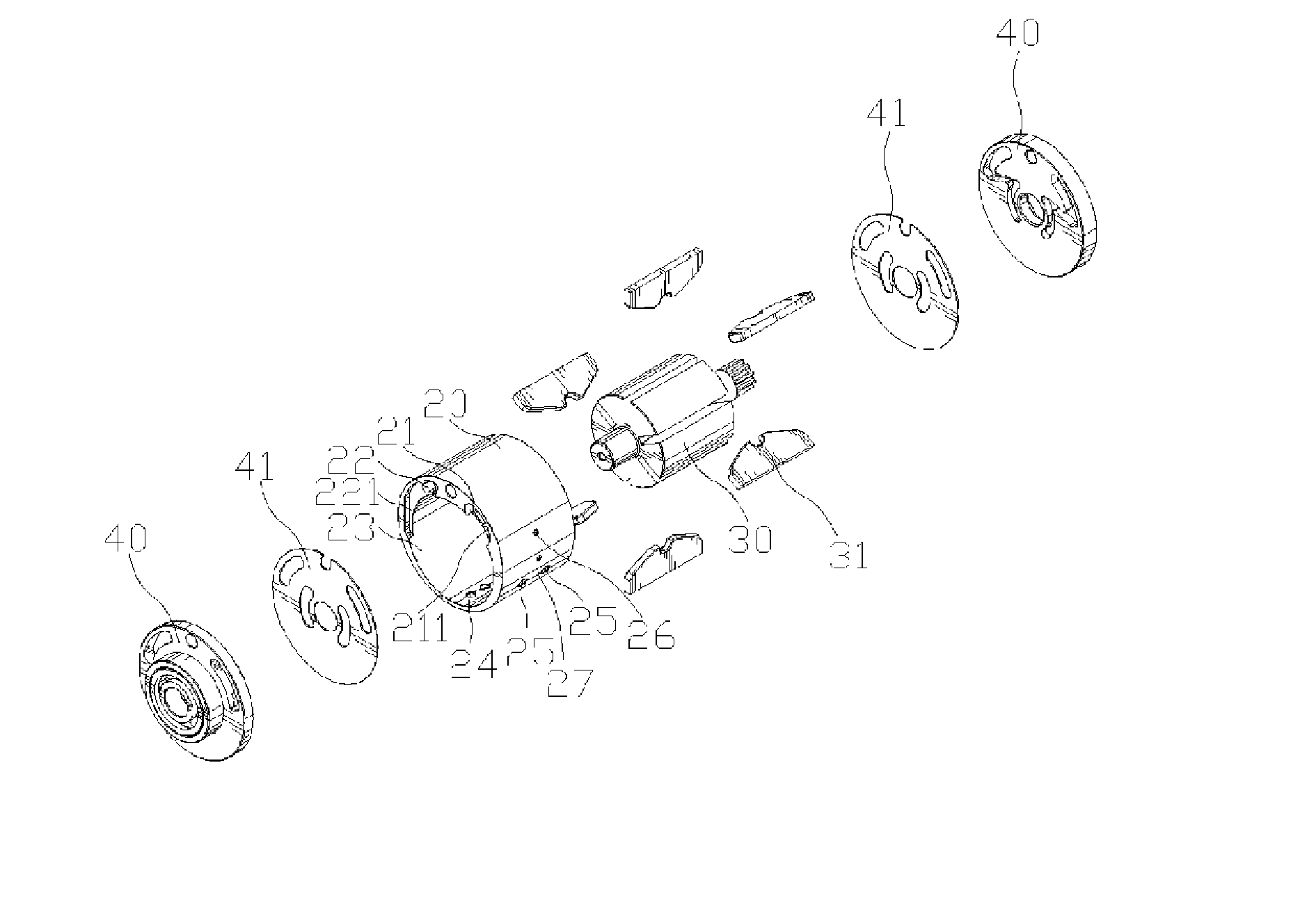
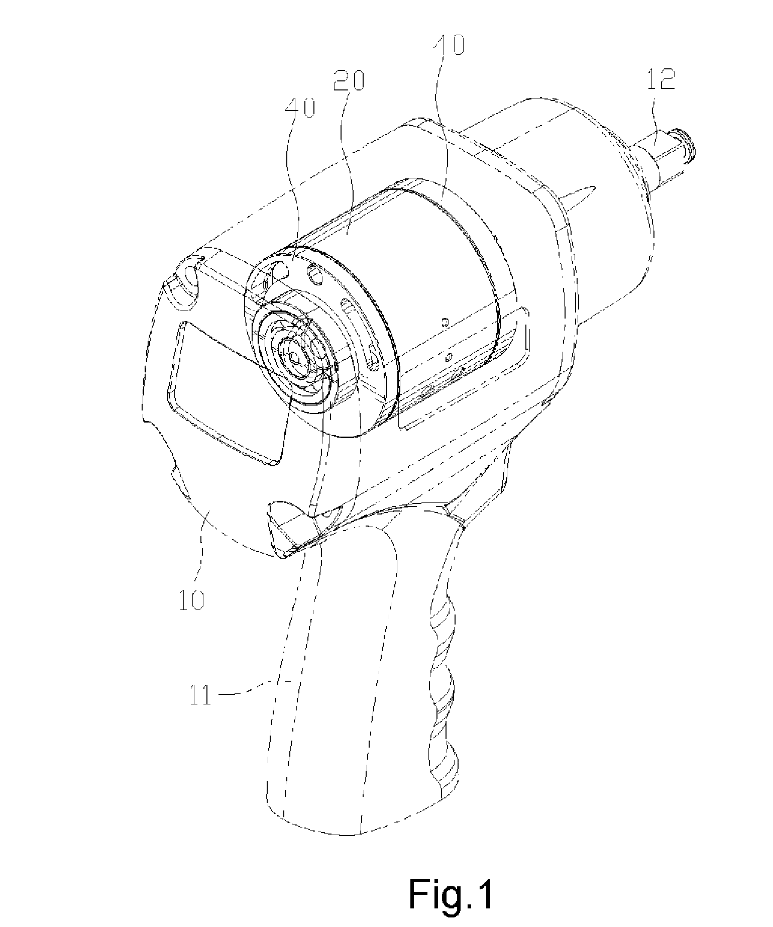
[0019] Referring to FIG. 1, there is shown a pneumatic tool according to the preferred embodiment of the present invention. The pneumatic tool includes a shell 10, a cylinder 20 positioned in the shell 10 and a rotor 30 for rotation in the cylinder 20.

[0020] The shell 10 includes a handle 11 for handling by a user.

[0021] A shaft 12 is inserted from the interior to the exterior of the shell 10. The shaft 12 includes an end connected to the rotor 30 and an opposite end for connection to a bit.

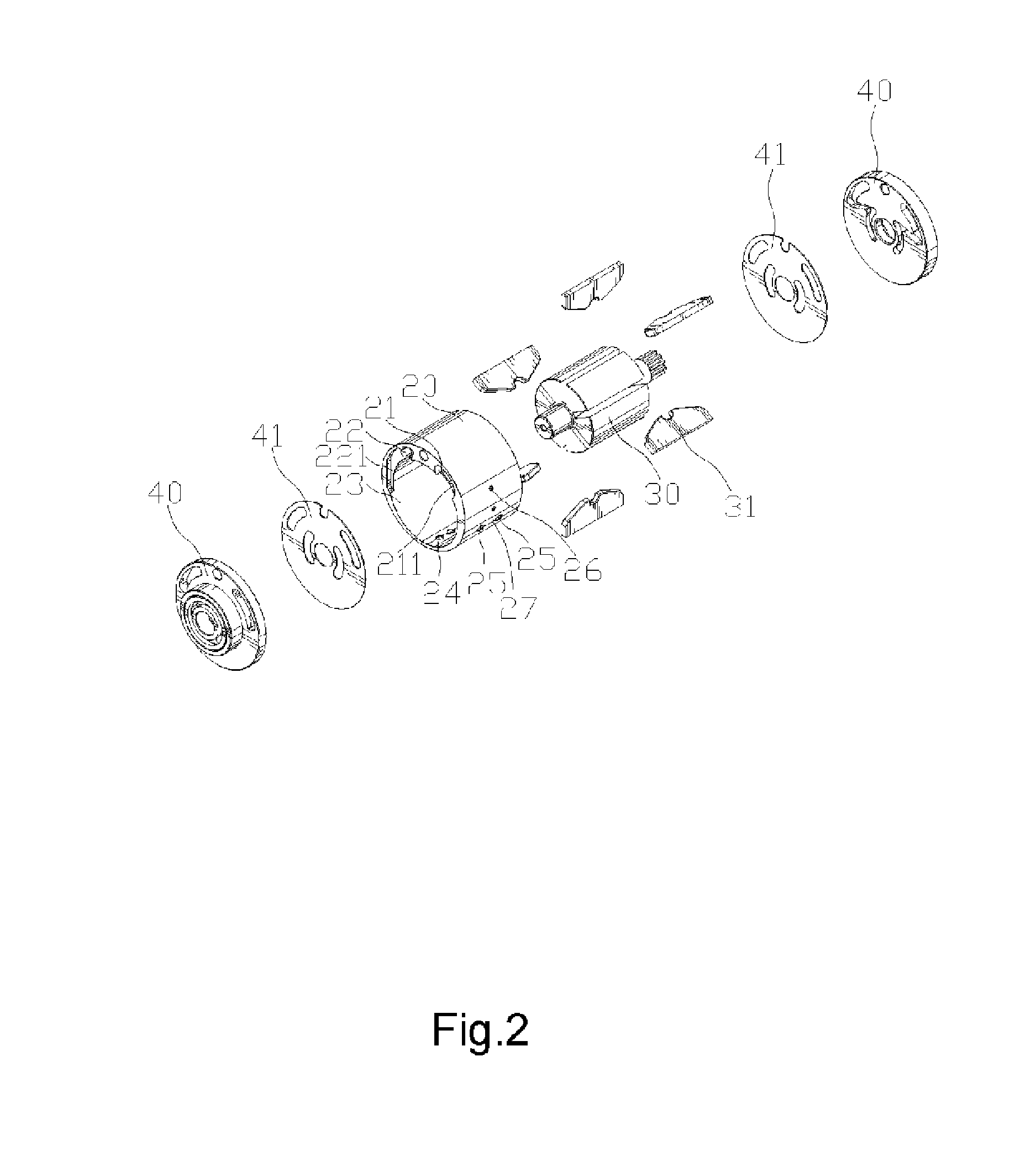
[0022] Referring to FIGS. 2 and 3, the cylinder 20 includes two ends that are made open and closed by means of two covers 40. A wearing-proof sheet 41 is provided between each of the covers 40 and related one of the ends of the cylinder 20.

[0023] The cylinder 20 includes a space 23 eccentrically defined therein so that the cylinder 20 includes a thick portion and a thin portion. Defined longitudinally in the thick portion of the cylinder 20 is a first intake 21 corresponding to a tightening m...


PUM


Abstract

A pneumatic tool includes a shell, a cylinder positioned in the shell, a rotor eccentrically positioned in the cylinder for rotation and a shaft connected to the rotor and inserted from the interior to the exterior of the shell. The cylinder defines a space for receiving the rotor, a first intake related to a tightening mode, a first channel for communicating the first intake with the space, a second intake related to a slackening mode, a second channel for communicating the second intake with the space, at least one outlet in communication with the space and at least one pressure-releasing vent in communication with the space between the outlet and the first intake so that air vents from the pressure-releasing vent before venting from the outlet in the tightening mode. Blades are connected to the rotor includes so that air can push the blades so as to rotate the rotor.

Description

BACKGROUND OF INVENTION [0001] 1. Field of Invention [0002] The present invention relates to pneumatic tools and, more particularly, to a pressure-stabilizing cylinder for pneumatic tools. [0003] 2. Related Prior Art [0004] A conventional pneumatic tool includes a switch operable for controlling the flow rate of air, thus controlling torque. The switch is however an instable design and may fail to provide stable torque because of excessive tolerance in the fabrication thereof or excessively high pressure of the air. [0005] Disclosed in Taiwanese Patent Publication No. 566300 is a cylinder set of a pneumatic tool. The cylinder set includes a cylinder 1 and a rotor 2 for rotation in the cylinder 1. The cylinder 1 eccentrically defines a space 16 so that it includes a thick portion and a thin portion. Intakes 11 and outlets 12 are defined in the thick portion of the cylinder 1 longitudinally. An outlet 13 is defined in the thin portion of the cylinder 1 transversely. [0006] The rotor 2...

Claims


Application Information

Patent Timeline
Patent Type & Authority Applications(United States)
IPC IPC(8): F03C2/00
CPCF01C1/3442F01C13/02F04C2250/10F04C2240/60F01C21/104
Inventor CHANG, JUI-SHENG
Owner PNEUTECH MANUFACTUER
Why Eureka
Try Eureka