Pressure gauge for chest drainage unit

Inactive Publication Date: 2007-09-20
TELEFLEX MEDICAL INC
View PDF11 Cites 0 Cited by
  • Summary
  • Abstract
  • Description
  • Claims
  • Application Information

AI Technical Summary

Benefits of technology

[0007] The foregoing needs are met, to a great extent, by the present invention, wherein in one aspect an apparatus is provided that in some embodiments a chest drainage unit that can accurately and effectively read the pressure indicative of the actual pressure in a patient.

Problems solved by technology

Current methods of indicating patient pressure are inaccurate by design.
However that is not always the case.

Method used


Image

  • Pressure gauge for chest drainage unit
  • Pressure gauge for chest drainage unit
  • Pressure gauge for chest drainage unit

Examples


Embodiment Construction

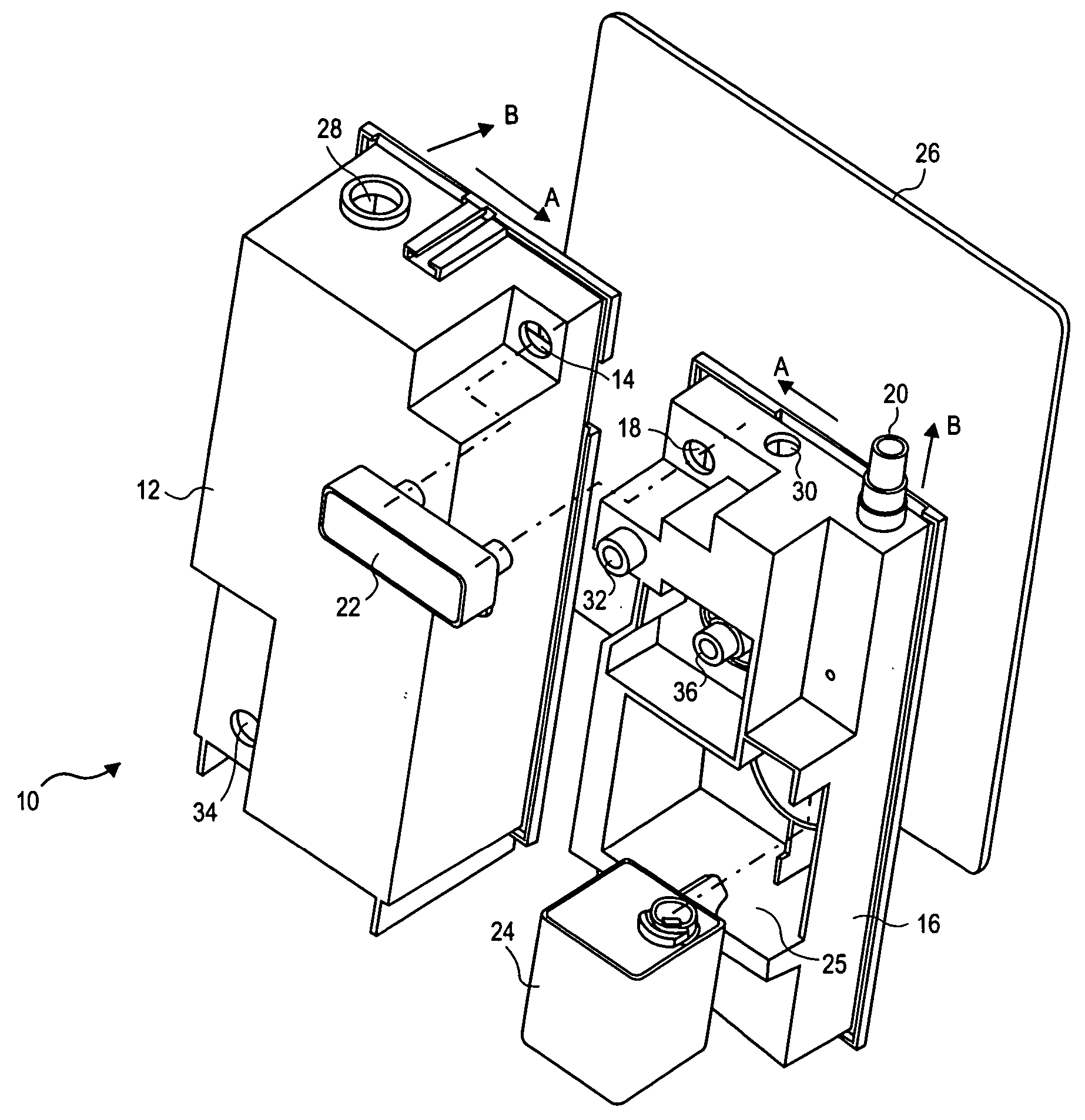
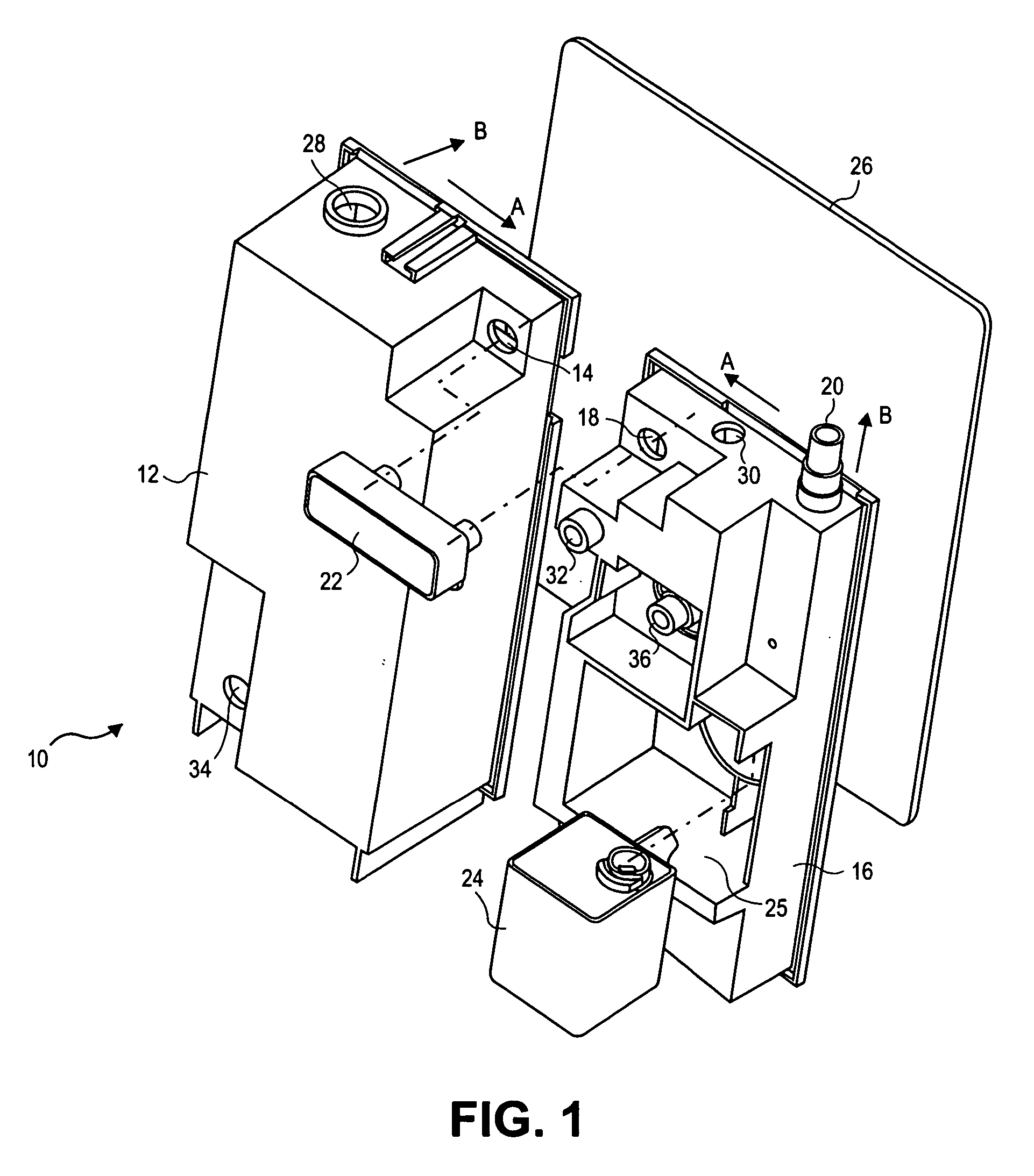
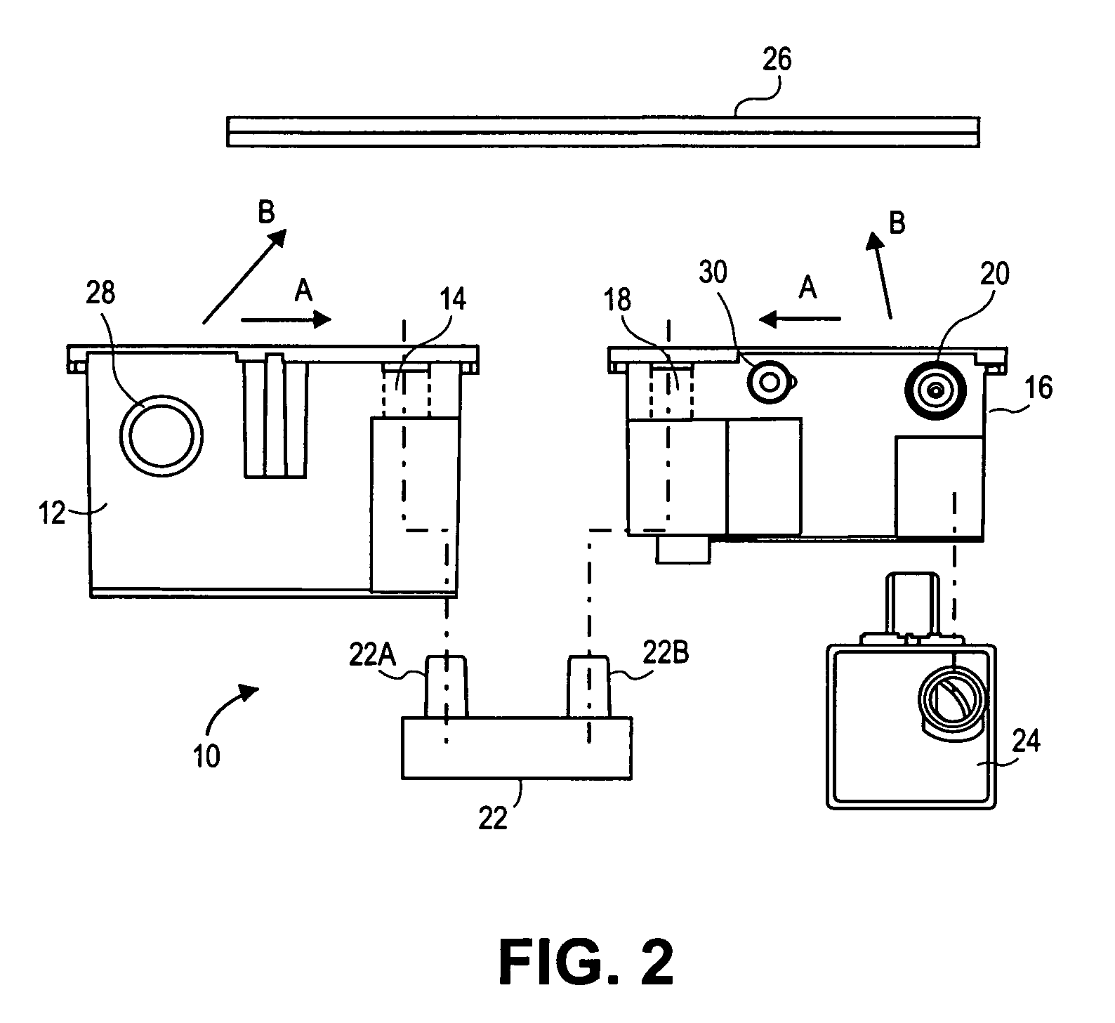
[0023] The invention will now be described with reference to the drawing figures, in which like reference numerals refer to like parts throughout. An embodiment in accordance with the present invention provides a pressure indicator for a chest drainage unit. The indicator includes an outer casing having a longitudinal axis and a first end with an opening exposed to ambient air and a second end with an opening coupled to communicate with the collection chamber inside a chest drainage unit for reading patient pressure. A linear force resistance element in the form of a spring compressed inside a bellows is disposed inside the outer casing and aligned along the longitudinal axis. An indicator cap is disposed inside the outer casing and coupled to a tip portion of the bellows element. The interior of the bellows communicates with the collection chamber pressure such that the spring and bellows expands and contracts inside the casing to indicate the degree of suction pressure in the coll...


PUM


Abstract

A pressure indicator for a chest drainage device includes an outer casing with a longitudinal axis and first and second end portions defining first and second openings. A flexible element is disposed inside the outer casing to define a collapsible pressure-holding inner space in fluid communication with the second opening. An indicator element is disposed inside the outer casing configured to translate along the longitudinal axis. The flexible element, indicator element and outer casing together define a variable interior space inside the outer casing in fluid communication with the first opening. A force resistance element is placed in the casing to resist the translation of the indicator element along at least one direction along the longitudinal axis when a pressure differential exists between the first and second openings.

Description

CROSS-REFERENCE TO RELATED APPLICATIONS [0001] The present application claims priority to and is a continuation-in-part of U.S. application Ser. No. 11 / 377,549, filed Mar. 17, 2006, now pending, the entire contents of which are incorporated herein by reference.FIELD OF THE INVENTION [0002] The present invention relates generally to medical devices. More particularly, the present invention relates to a pressure indicating means in a chest drainage unit. BACKGROUND OF THE INVENTION [0003] Chest drainage devices and systems and more particularly suction drainage systems and devices for removing gases and / or liquids from medical patients, such as from the pleural cavity, by means of a pressure differential, are well known in the art. For many years, the standard apparatus for performing the evacuation of the pleural cavity was a drainage system known as the “3-bottle set-up” which includes a collection bottle or chamber, a water seal bottle, and a suction control bottle. A catheter runs...

Claims


Application Information

Patent Timeline
IPC IPC(8): A61M27/00
CPCA61M1/0009A61M2205/3331A61M1/0013A61M1/61A61M1/67
Inventor PHUNG, TRINH D.DREYER, ERICH A.MOORE, DOUGLAS W.
Owner TELEFLEX MEDICAL INC
Why Eureka
Try Eureka