
Method for modeling and documenting a network

Inactive Publication Date: 2007-09-20
ARIZONA PUBLIC SERVICE
View PDF19 Cites 23 Cited by
  • Summary
  • Abstract
  • Description
  • Claims
  • Application Information

AI Technical Summary

Benefits of technology

[0007] Accordingly, it is an advantage of the present invention that a computer-based method and a computer program are provided for documenting a network.
[0008] It is another advantage of the present invention that a computer-based method and computer program are provided that model and document network elements and relationships in a common format.
[0009] Another advantage of the present invention is that a computer-based method and executable code are provided that allow for straightforward extension of a network model and network documentation.
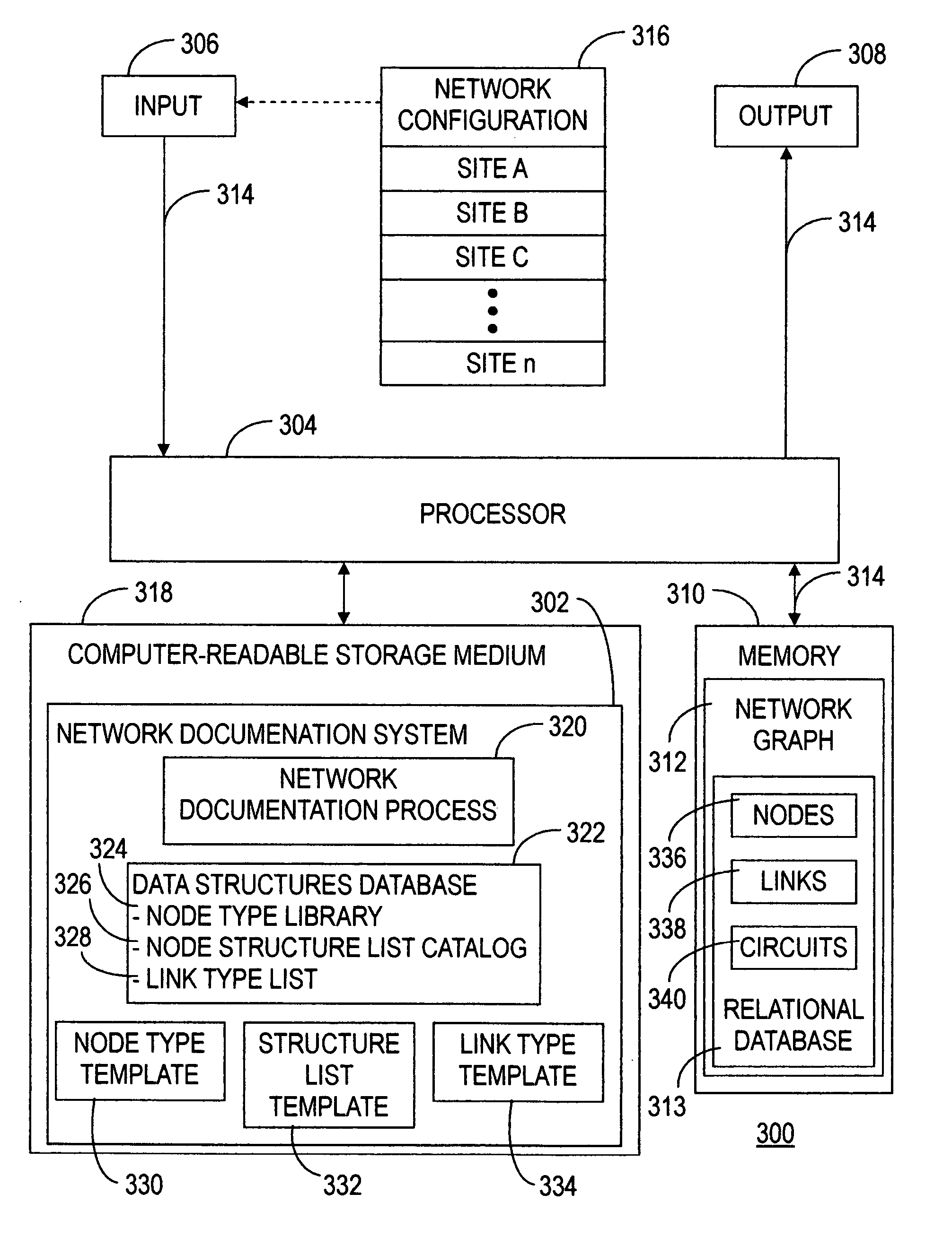
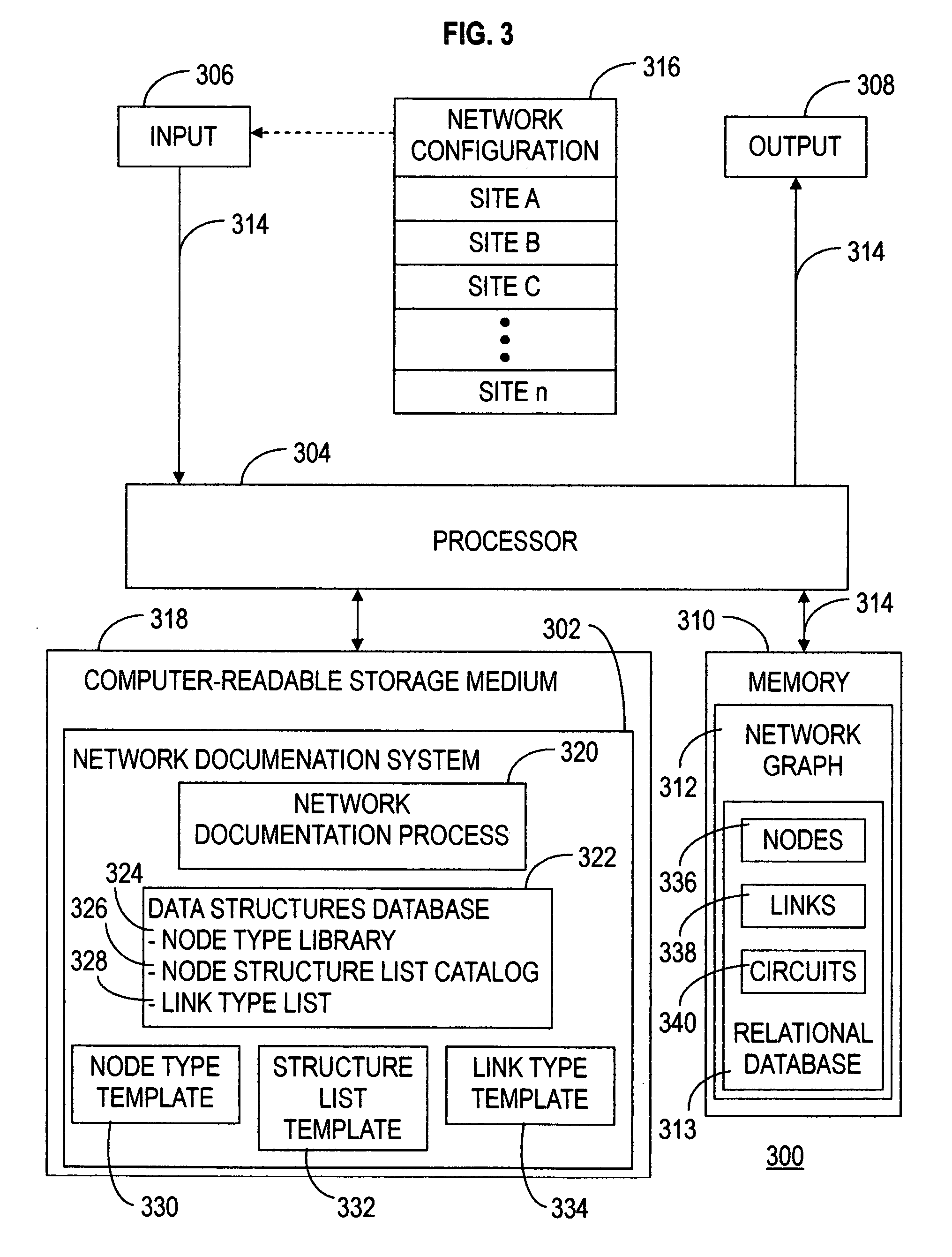
[0010] The above and other advantages of the present invention are carried out in one form by a computer-based method for documenting a network. The method calls for receiving a configuration of elements within the network and representing the elements by nodes in a model of the network, each of the nodes being defined by one of a plurality of node types, and each of the node types governing structure rules for descendable ones of the nodes. The nodes are presented in a network graph in accordance with the structure rules to document the network.
[0011] The above and other advantages of the present invention are carried out in another form by a computer-readable storage medium containing a computer program for documenting a network. The computer program includes a library of node types constructed in accordance with a node type template. The node type template includes a structure rule field for entry of structure rules, the structure rules identifying descendable ones of the node types. The computer program further includes executable code for instructing a processor to create a network graph, the executable code instructing the processor to perform operations including receiving a configuration of elements within the network and representing the elements by nodes in a model of the network. The representing operation calls for selecting, for each of the nodes, a node type defining the node from the library of node types and obtaining a range of the descendable node types for the node in response to the structure rules defining the node. The node represents a first element in the network. A child node, defined by a first node type within the range of node types is created. The child node represents a second element in the network, the second element being descendent from the first element. The child node is presented in association with the node in a network graph to document the network.

Problems solved by technology

Such networks have grown to become complex, heterogeneous environments spanning multiple locations and platforms.
As networks have grown ever more complex, simple hand drawn sketches and spreadsheets have become inadequate for thorough documentation of such networks.
That is, such networks are far too vast, varied, and complex to be understood completely without comprehensive documentation.
Many data models are so radically different that, even though the same information may be required by, and embedded in, multiple models, variations in the form and organization of that information within the disparate models makes it extremely difficult to move from one system to another, or to compare the information for consistency from one system to another.
Additionally, such data models often cannot support the introduction of new technologies into their data structures.
Thus, with existing modeling techniques, new databases or complex extensions to existing databases are required to support new communication technologies or application specific information.
The result is a series of disjointed databases with appended tables, all of which cannot be operated, managed, or understood by a single individual.
Network complexity necessitates documentation that is sharable and available to those who are responsible for maintaining the network.

Method used


Image

  • Method for modeling and documenting a network
  • Method for modeling and documenting a network
  • Method for modeling and documenting a network

Examples


Embodiment Construction

[0031] The present invention enables efficient modeling and documentation of elements and relationships in a network through the utilization of a common format. This common format allows for straightforward extension of a network model and network documentation.

[0032] The following is a glossary of terminology used herein:

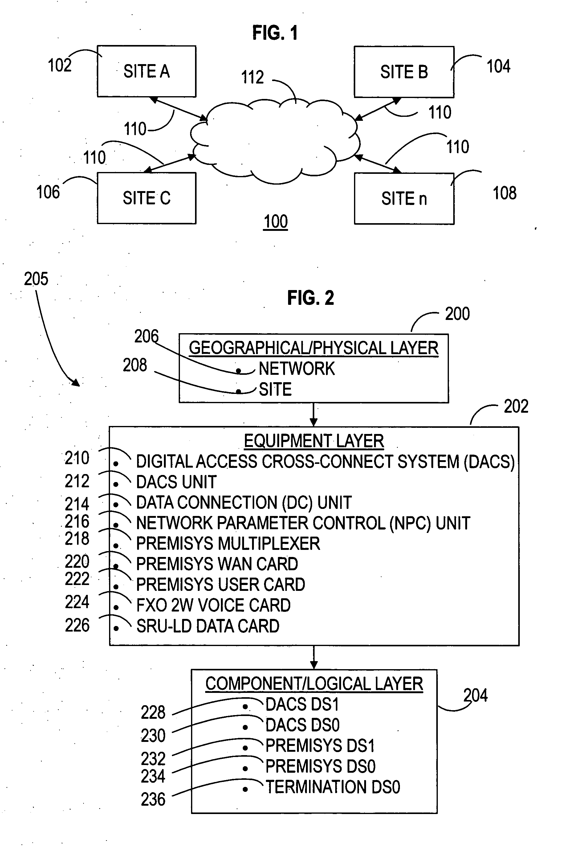
[0033] Network: is any interconnected group or system. For example, a telecommunications network is a network of elements and connections arranged so that information may be passed from one part of the network to another.

[0034] Network Element: any physical or logical point of interest in a network.

[0035] Network Connection: a path between two directly connected network elements in a network.

[0036] Network Data Path: the route for information between two network elements in a network—particularly between two network elements that are not necessarily directly connected.

[0037] Site: is a geographic location in the network at which a collection of network elemen...


PUM


Abstract

A network documentation system computer program (302) for documenting a network (100) receives a configuration of elements (205) within the network (100). Methodology (320) of the program represents the elements (205) by nodes (336) in a model of the network (100). Each of the nodes (336) is defined by one of a plurality of nodes types (402), and each of the node types (402) governs structure rules (504) for child nodes (808) and connectivity rules (508) for defining links (338) between nodes (336). The nodes (336) are presented in a network graph (312) in accordance with the structure rules (504) to document the network (100), with the child nodes (808) associated with their respective parent nodes (806). The links (338) are depicted between the nodes (336) in the network graph (312) in accordance with the connectivity rules (508), and represent connections between pairs of elements (205) in the network (100).

Description

TECHNICAL FIELD OF THE INVENTION [0001] The present invention relates to the field of networks. More specifically, the present invention relates to a network management system for documenting a network. BACKGROUND OF THE INVENTION [0002] Complex networks, such as telecommunications networks, enterprise networks, and the like, typically include one or more types of specialized components that interconnect on various levels. Such networks have grown to become complex, heterogeneous environments spanning multiple locations and platforms. As networks have grown ever more complex, simple hand drawn sketches and spreadsheets have become inadequate for thorough documentation of such networks. That is, such networks are far too vast, varied, and complex to be understood completely without comprehensive documentation. Consequently, automated mechanisms for modeling, documenting, and managing the networks have emerged. These mechanisms are generally implemented in the form of computer program...

Claims


Application Information

Patent Timeline
IPC IPC(8): G06F17/50
CPCH04L41/12
Inventor ARNONE, JOSEPH A.FLEMING, WILLIAM E.RAEL, CHRISTOPHER J.
Owner ARIZONA PUBLIC SERVICE
Learn More