Eureka AIR delivers breakthrough ideas for toughest innovation challenges, trusted by R&D personnel around the world.

Bow

a bow and bowstring technology, applied in the field of bows, can solve the problems of reducing the draw length and powerstroke of the bow, sacrificing speed, and requiring cam synchronization, so as to reduce the force required to draw the bowstring, increase the powerstroke, and increase the speed of the arrow

Active Publication Date: 2007-09-27
KEMPF JAMES J
View PDF12 Cites 2 Cited by
  • Summary
  • Abstract
  • Description
  • Claims
  • Application Information

AI Technical Summary

Benefits of technology

[0006]In the advantage provided by this invention, a bow is provided which is of a low-cost, simple manufacture.
[0007]Advantageously, this invention provides a bow of a compact, lightweight construction.
[0009]Advantageously, this invention provides a bow which reduces the force required to draw the bowstring.
[0010]Advantageously, in the preferred embodiment of this invention, a bow is provided with a pair of limbs extending upwardly and rearwardly from a riser. A pulley is coupled to one riser while a cam is coupled to the other. A first string is coupled between the pulley and cam, as is a second string which is located on the side of the pulley and cam closest to the riser. An arrow is notched to the second string, which is drawn and fired. By utilizing the second string to launch the arrow, and drawing the second string from the forward portion from the cam and pulley, the powerstroke is increased, thereby allowing increased speed of the arrow with a reduction in the effort required to launch the arrow.

Problems solved by technology

One drawback associated with such cams is the requirement that cams be “synchronized” to prevent lateral travel of the rear of the arrow during launch.
However, reducing the length of the bow risers, and / or sweeping the risers in a more rearward orientation, often reduces the draw length and powerstroke of the bow.
Reducing the powerstroke simultaneously sacrifices speed and increases the draw weight required to obtain the desired performance.

Method used


Image

  • Bow
  • Bow
  • Bow

Examples


Embodiment Construction

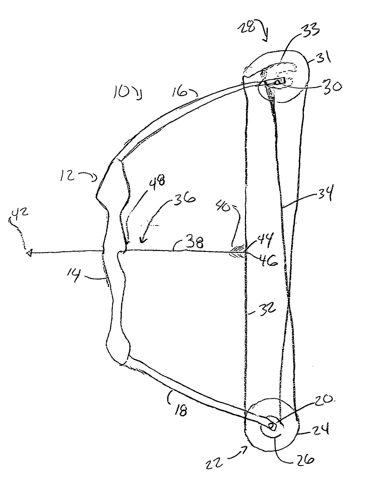
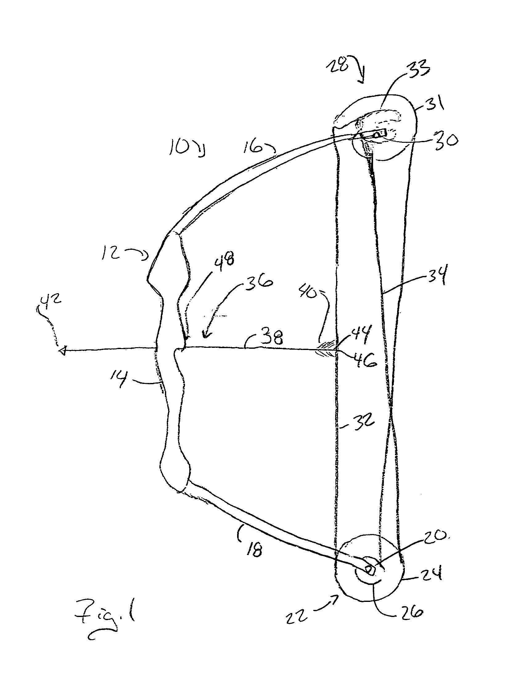
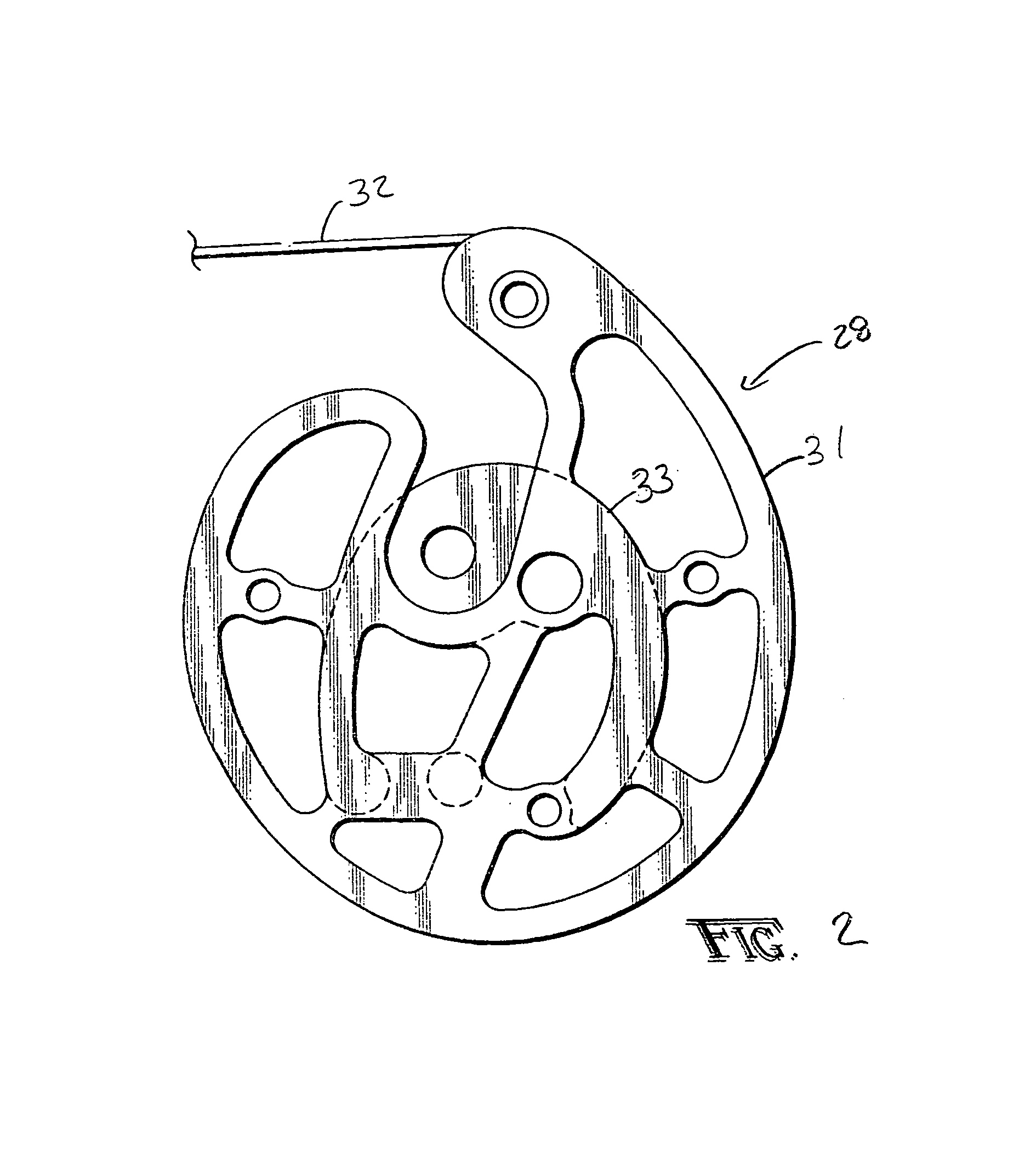
[0016]A bow according to the present invention is shown generally as (10) in FIG. 1. The bow (10) includes a riser (12) provided with a handle (14) in a manner such as that known in the art. Coupled to the riser (12) is a first limb (16) and second limb (18). A pulley is journaled to the first limb (16) with an axle (20) which acts as journal point. The pulley (22) has an outer track (24) and an inner track (26). The pulley (22) is preferably journaled to the first limb (16) in a manner which positions a portion of the pulley (22) rearward and outward of the space defined between the limbs (16) and (18). As shown in FIG. 1, a second string guide, which in the preferred embodiment is a cam (28), is journaled to the second limb (18) at a second journal point (30). The cam (28) is journaled to the second limb (18) so that at least a portion of the cam (28) extends rearward and outward of the area defined between the limbs (16) and (18). The cam (28) is preferably constructed as shown i...


PUM


Abstract

A bow having an increased powerstroke allowing for reduced draw weight and increased speed. The bow is provided with a riser and a pair of limbs. A pulley is coupled to one limb and a cam is coupled to the other at a first journal point and second journal point respectively. The powerstroke is increased by locating the bowstring on the pulley and cam between the riser and the journal points.

Description

Background of the Invention[0001]1. Field of the Invention[0002]The present invention relates in general to an improved bow and particularly to a bow having an improved powerstroke.[0003]2. Description of the Prior Art[0004]Bows are well known in the art. Over the past several decades, bows have been consistently improved with technological innovations which have dramatically increased performance. One improvement has been the provision of cams on the bow to increase the mechanical advantage associated with the draw of the bowstring. One drawback associated with such cams is the requirement that cams be “synchronized” to prevent lateral travel of the rear of the arrow during launch. Accordingly, the prior art has utilized a single cam arrangement in association with a pulley, such as that described in McPherson, U.S. Letters Pat. No. 6,267,108, which substantially reduces the problem associated with “synchronization” and rear travel of the arrow.[0005]For climbing into trees and hun...

Claims


Application Information

Patent Timeline
IPC IPC(8): F41B5/10
CPCF41B5/105F41B5/10
Inventor KEMPF, JAMES J.
Owner KEMPF JAMES J
Why Eureka
Eureka Blog
Learn More