Luminance control device, display device, luminance control method, luminance control program, and recording medium storing the luminance control program

a control device and luminance technology, applied in the field of luminance control devices, can solve problems such as complicated control processing of luminance, and achieve the effect of preventing the breakage of the display section

Inactive Publication Date: 2007-09-27
PANASONIC CORP
View PDF3 Cites 13 Cited by
  • Summary
  • Abstract
  • Description
  • Claims
  • Application Information

AI Technical Summary

Benefits of technology

[0007]An object of the present invention is to provide a luminance control device, a display device, a luminance control method, a luminance control program capable of controlling the luminance of the display section so that breakage of the display section can be prevented, and a recording medium storing the luminance control program

Problems solved by technology

Accordingly, for example, control processing for the luminance may become complicated.

Method used


Image

  • Luminance control device, display device, luminance control method, luminance control program, and recording medium storing the luminance control program
  • Luminance control device, display device, luminance control method, luminance control program, and recording medium storing the luminance control program
  • Luminance control device, display device, luminance control method, luminance control program, and recording medium storing the luminance control program

Examples


Embodiment Construction

)

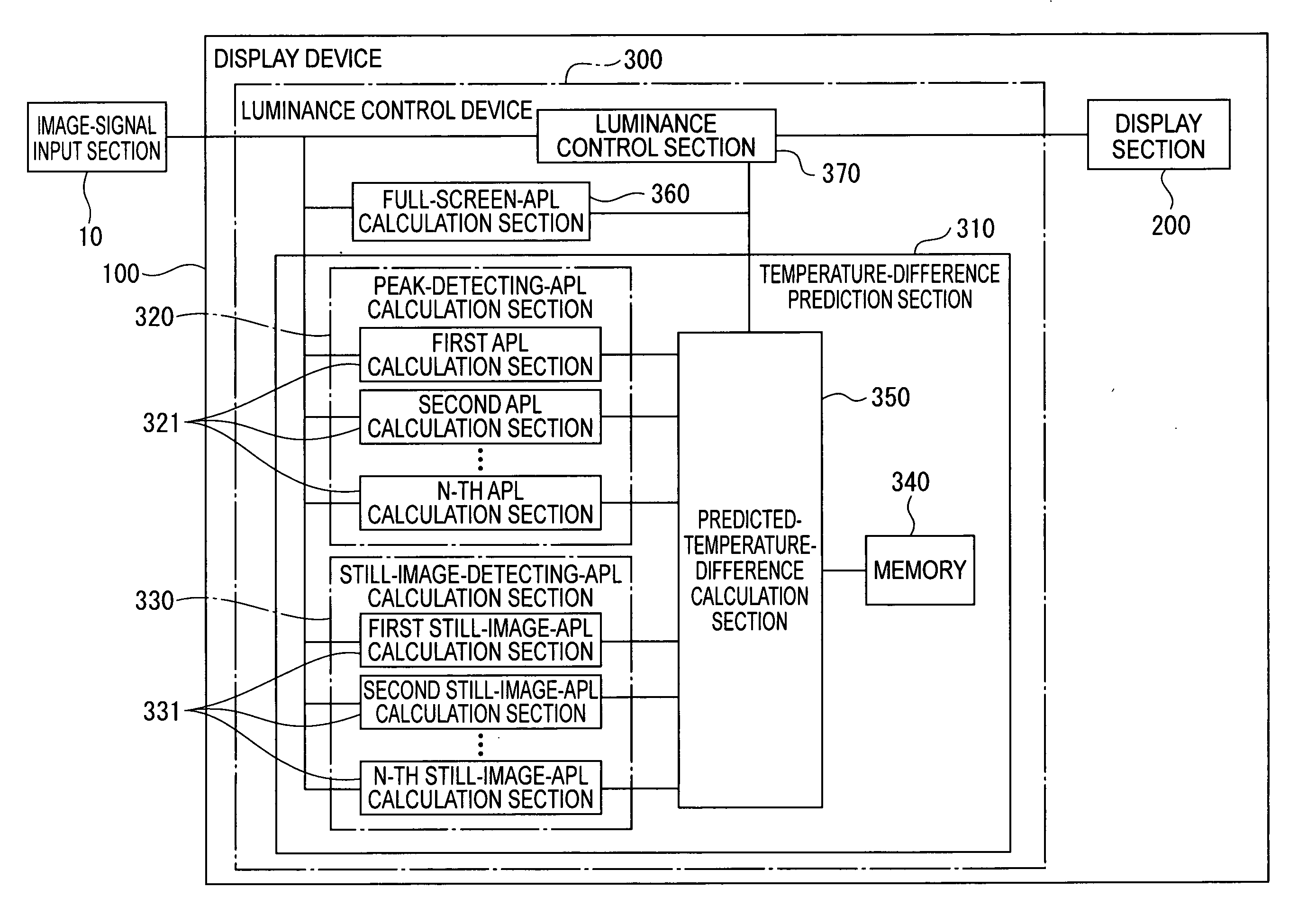
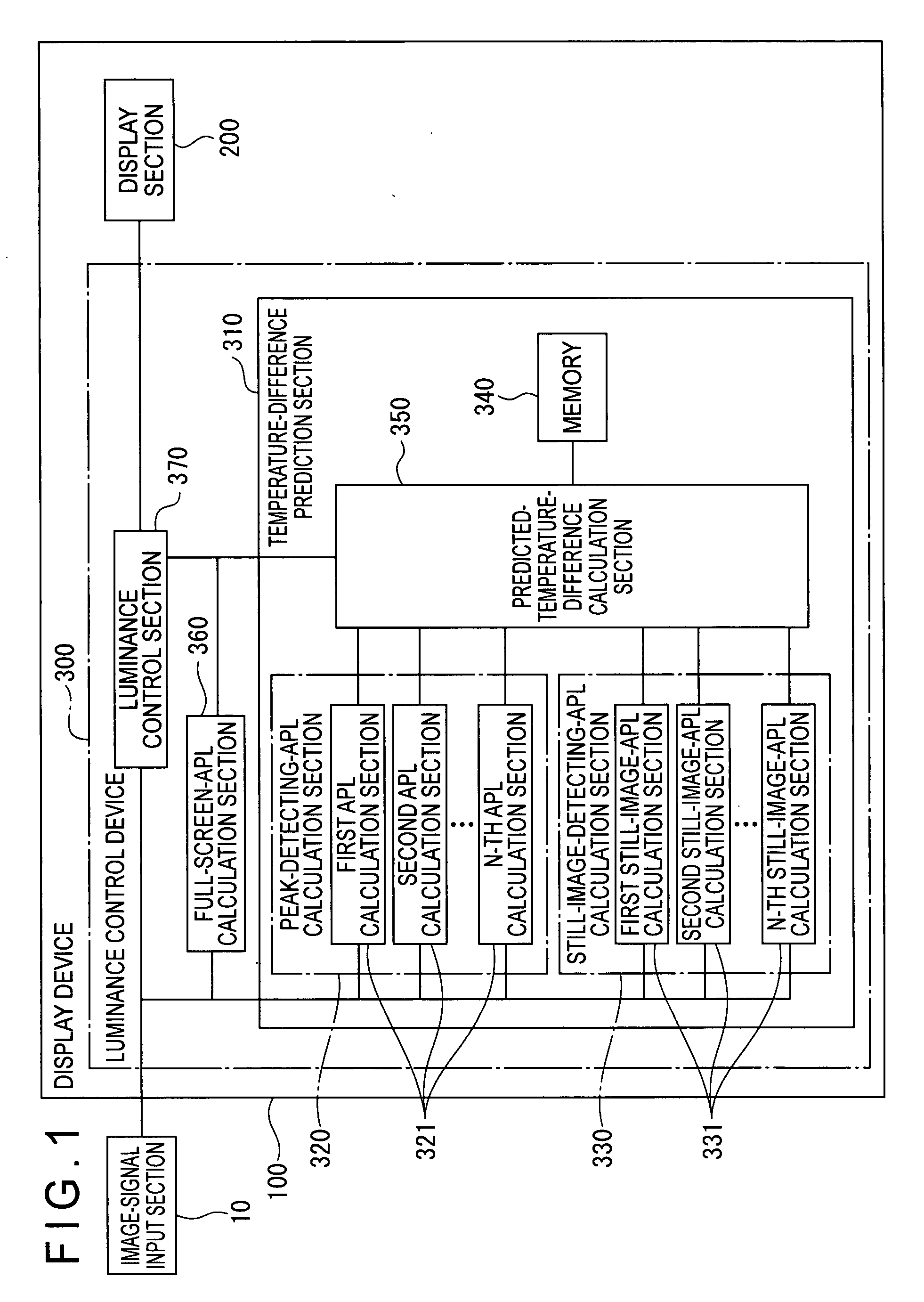
[0038]An embodiment of the present invention will be described with reference to the attached drawings. In this embodiment, a display device that controls luminance of an image to a state of preventing breakage of a display section will be exemplified.

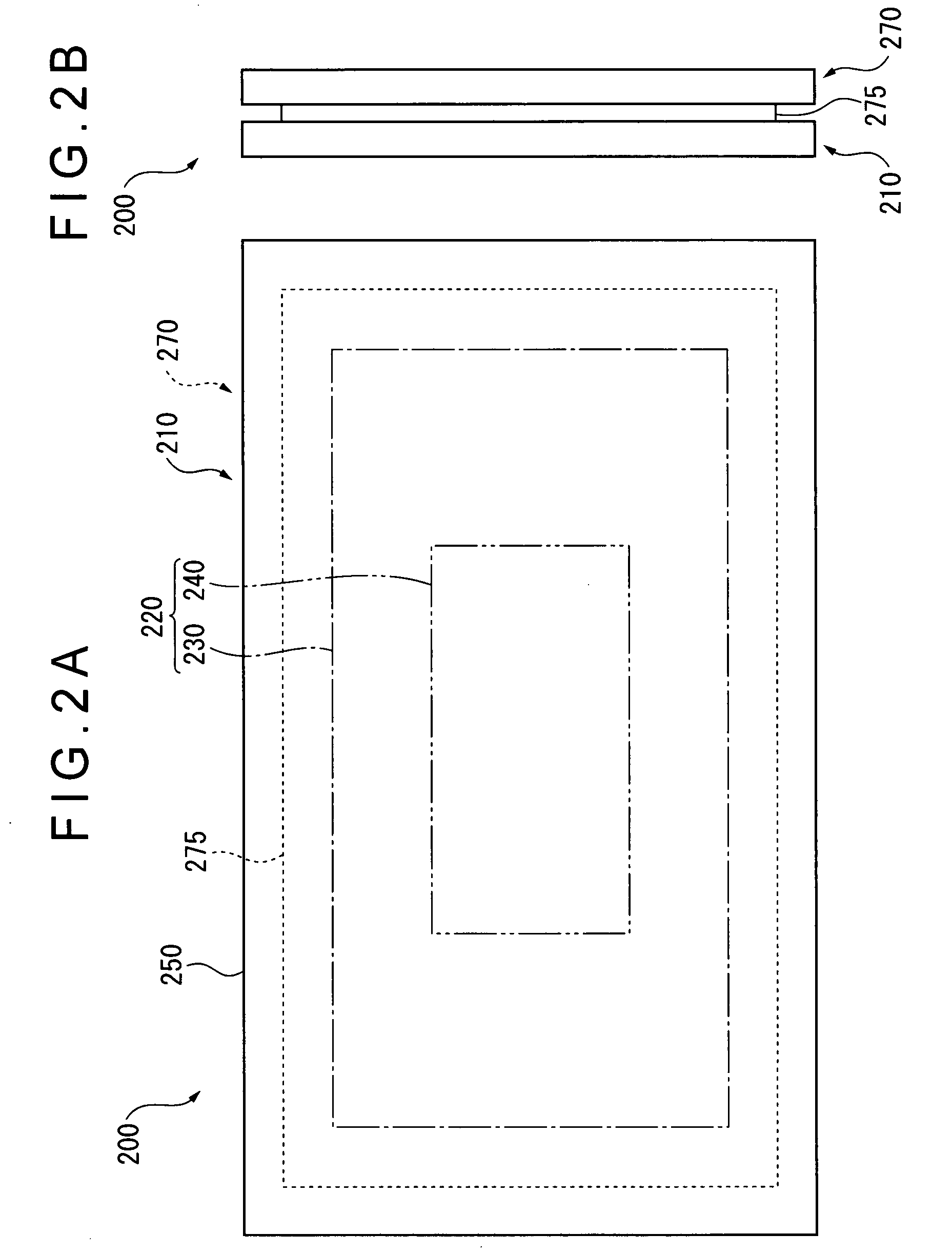
[0039]FIG. 1 is a block diagram showing a schematic arrangement of the display device according to the embodiment of the present invention. FIGS. 2A and 2B are schematic views each showing a schematic arrangement of a display section, where FIG. 2A is a plan view of the display section; and FIG. 2B is a side view thereof. FIGS. 3 to 6 are schematic views each showing blocks for which peak-detecting APLs and still-image-detecting APLs are to be calculated. FIG. 7 is a graph showing relationships between a time and a temperature in a left / right-side peripheral display area and an outer peripheral area at the times of the respective APLs. FIG. 8 is a graph showing relationships between the time and a temperature difference between the le...


PUM


Abstract

Provided is a display device (100) which predicts a predicted temperature difference between a peripheral display area and an outer peripheral area of a display section (200) based on an input image signal from an image-signal input section (10). When the predicted temperature difference is a set reference value or more, the display device (100) controls luminance of an image displayed on the peripheral display area so as to be lowered. Therefore, the predicted temperature difference is predicted by using only the input image signal, and the luminance of the image displayed on the peripheral display area can be appropriately controlled without performing a calculation using the predicted temperature difference. Hence, such a luminance control for preventing breakage of the display section (200) can be easily performed.

Description

BACKGROUND OF THE INVENTION[0001]1. Field of the Invention[0002]The present invention relates to a luminance control device, a display device, a luminance control method, and a luminance control program, for controlling luminance of an image displayed on a display section, and to a recording medium storing the luminance control program.[0003]2. Description of Related Art[0004]Heretofore, there has been known an arrangement in which luminance of an image is adjusted in order to prevent breakage of a display section (see, for example, JP 3270435 B, from the left column of page 4 to the left column of page 11).[0005]In the arrangement described in JP 3270435 B, an estimated temperature value representing a temperature of an outer peripheral portion of a display screen of a plasma display panel (PDP) is obtained from a picture signal. Further, an estimated temperature difference value is obtained by subtracting, from the estimated temperature value, a reference value representing a temp...

Claims


Application Information

Patent Timeline
Patent Type & Authority Applications(United States)
IPC IPC(8): G09G3/36G09G3/20G09G3/28G09G3/288G09G3/291G09G3/298H04N5/66
CPCG09G3/20G09G3/288G09G2310/0232G09G2360/16G09G2320/0626G09G2320/103G09G2330/04G09G2320/046
Inventor YOSHIDA, TAKUMA
Owner PANASONIC CORP
Why Eureka
Try Eureka