Display and method thereof

a technology of display and display plate, applied in the field of electronic technologies, can solve the problems of spacer disorder or moving to undesirable locations, substrate separation or separation from the spacer, cracking and/or tearing of the electrode and/or other hard coat fixed to the surface of the substrate, etc., to achieve the effect of reducing or effectively preventing disordered spacers, reducing the risk of cracking of electrodes and other solid coats of the substrate, and increasing the reliability of flexible displays

Active Publication Date: 2007-09-27
SAMSUNG DISPLAY CO LTD
View PDF14 Cites 22 Cited by
  • Summary
  • Abstract
  • Description
  • Claims
  • Application Information

AI Technical Summary

Benefits of technology

[0011]An exemplary embodiment provides a flexible display with enhanced reliability and better picture quality in spite of the adverse outside force applied to the display.
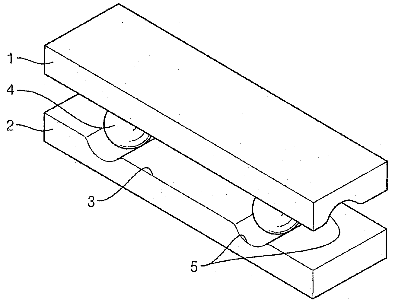
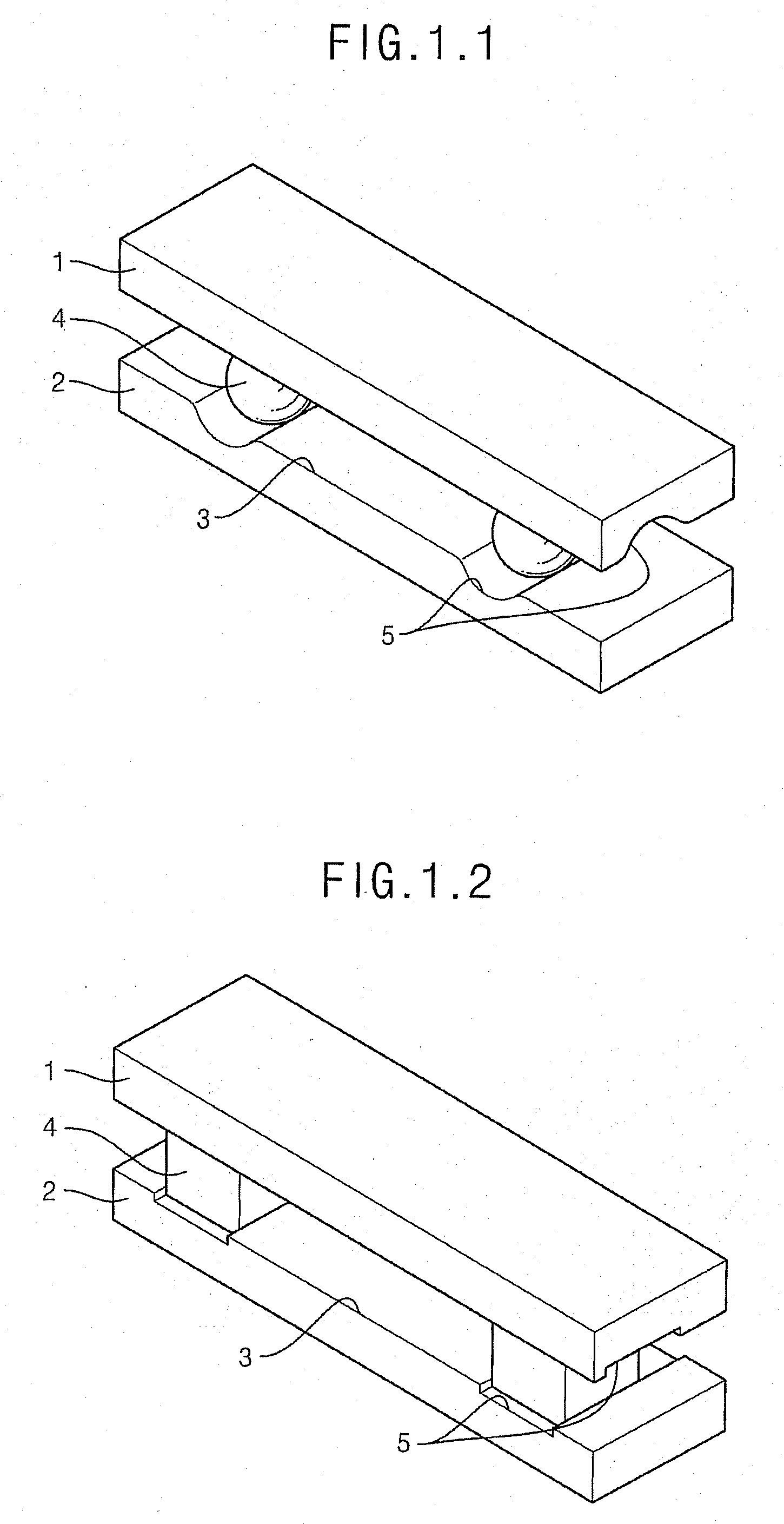
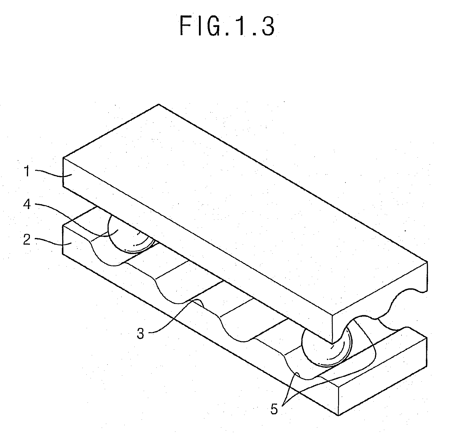
[0024]An exemplary embodiment provides increased reliability of a flexible display and picture quality in spite of an outside force applied to the display. A disordering of the spacers is reduced or effectively prevented, a clearance between the substrates is maintained and cracking of electrodes and other solid coats of the substrates is minimized. A lateral arrangement of the channels on facing (e.g., opposing) surfaces of the substrates is fixed due to placement of the spacers in the cross-points of the channels in facing surfaces of the substrates.

Problems solved by technology

In displays with flat substrates and spacers, an exterior action (e.g., external force) on the display panel, in particular, a bend, can result in spacers disordering or moving to undesirable locations.
Such disordering is caused by the lack of reliable fixation of the spacers.
Moreover, there is a chance that a substrate would be separated or detached from the spacers when the external force is applied to the display.
Other disadvantages may include cracking and / or tearing of the electrodes and / or other hard coats fixed to the surface of substrates when an external force is applied and the display is bent.
The cracking or tearing is often pronounced in places of contact of an electrode with the spacers, applying additional pressure (e.g., overload) on the electrodes.
The above drawbacks decrease reliability of the display and the picture quality under the impact of an outside force.

Method used


Image

  • Display and method thereof
  • Display and method thereof
  • Display and method thereof

Examples


Embodiment Construction

[0029]The invention is described more fully hereinafter with reference to the accompanying drawings, in which exemplary embodiments of the invention are shown. This invention may, however, be embodied in many different forms and should not be construed as limited to the exemplary embodiments set forth herein. Rather, these embodiments are provided so that this disclosure will be thorough and complete, and will fully convey the scope of the invention to those skilled in the art. In the drawings, the size and relative sizes of layers and regions may be exaggerated for clarity.

[0030]It will be understood that when an element or layer is referred to as being “on” another element or layer, the element or layer can be directly on another element or layer or intervening elements or layers. In contrast, when an element is referred to as being “directly on” another element or layer, there are no intervening elements or layers present. Like numbers refer to like elements throughout. As used h...


PUM

PropertyMeasurementUnit
angleaaaaaaaaaa
angleaaaaaaaaaa
angleaaaaaaaaaa

Abstract

A flexible display including a first flexible substrate and a second flexible substrate, a plurality of electrodes and control microcircuits disposed on inner surfaces of both substrates, first channels disposed on the inner surface of the first flexible substrate and extending in a first direction, second channels disposed on the inner surface of the second flexible substrate and extending in a second direction, and a plurality of spacers disposed between the substrates. The inner surfaces of the substrates are substantially parallel and facing each other. The first direction and the second direction of the channels are inclined relative to each other. The spacers are disposed between the substrates in cross-points of the first channels and the second channels.

Description

[0001]This application claims priority to Russian Patent Application No. 2006-109536 filed on Mar. 27, 2006, and all the benefits accruing therefrom under 35 U.S.C. §119, the contents of which are herein incorporated by reference in its entirety.BACKGROUND OF THE INVENTION[0002]1. Field of the Invention[0003]The invention relates to electronic technologies, and, more precise, to devices for controlling intensity, color, phase, polarization or direction of light, in particular, to flexible displays.[0004]2. Description of the Related Art[0005]Flexible displays (e.g., liquid crystal, organic, electroluminescent, electrochromic) include plastic or metal substrates with electrodes and driving microcircuits on their interior surfaces. Between substrates are paddings, otherwise known as spacers. Substrates of flexible displays normally have flat surfaces.[0006]Spacers are used for maintenance of the uniform clearance between the substrates and to assemble the substrates together. Spacers ...

Claims


Application Information

Patent Timeline
Patent Type & Authority Applications(United States)
IPC IPC(8): G02F1/1339
CPCG02F1/13392G02F1/133305G02F1/1339
Inventor BELYAEV, VIKTOR VASILYEVICH
Owner SAMSUNG DISPLAY CO LTD
Why Eureka
Try Eureka