
Multi-chip light emitting device lamps for providing high-cri warm white light and light fixtures including the same

a light-emitting device and light-emitting lamp technology, which is applied in the direction of semiconductor devices for light-emitting sources, lighting and heating apparatus, light source combinations, etc., can solve the problems of low cri of light generated by phosphor-based solid-state light sources, difficult to obtain high efficiency, and inability to achieve high efficiency

Active Publication Date: 2007-09-27
CREELED INC
View PDF99 Cites 673 Cited by
  • Summary
  • Abstract
  • Description
  • Claims
  • Application Information

AI Technical Summary

Problems solved by technology

While it may be possible to achieve fairly high luminous efficacy and / or color rendering with such lamps, wavelength ranges may exist in which it may be difficult to obtain high efficiency (e.g., approximately 550 nm).
However, light generated from a phosphor-based solid state light source may have a relatively low CRI.
In addition, while light generated by such an arrangement may appear white, objects illuminated by such light may not appear to have natural coloring due to the limited spectrum of the light.
For example, as the light from a blue LED covered by a yellow phosphor may have little energy in the red portion of the visible spectrum, red colors in an object may not be well-illuminated.
As a result, the object may appear to have an unnatural coloring when viewed under such a light source.
However, over time, the red-emitting phosphor particles may be subject to greater degradation than the yellow-emitting phosphor particles, which may decrease the useful lifetime of the light source.

Method used


Image

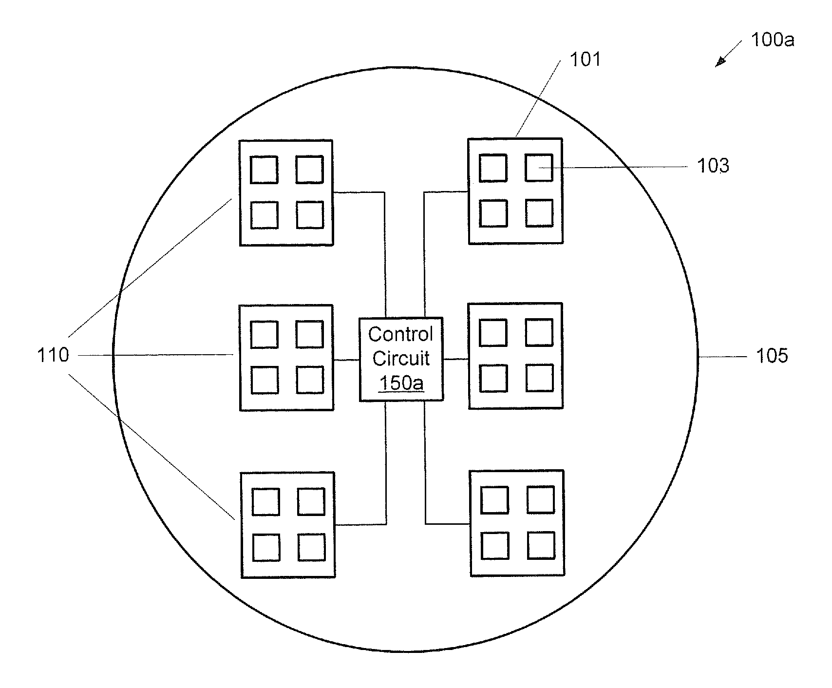
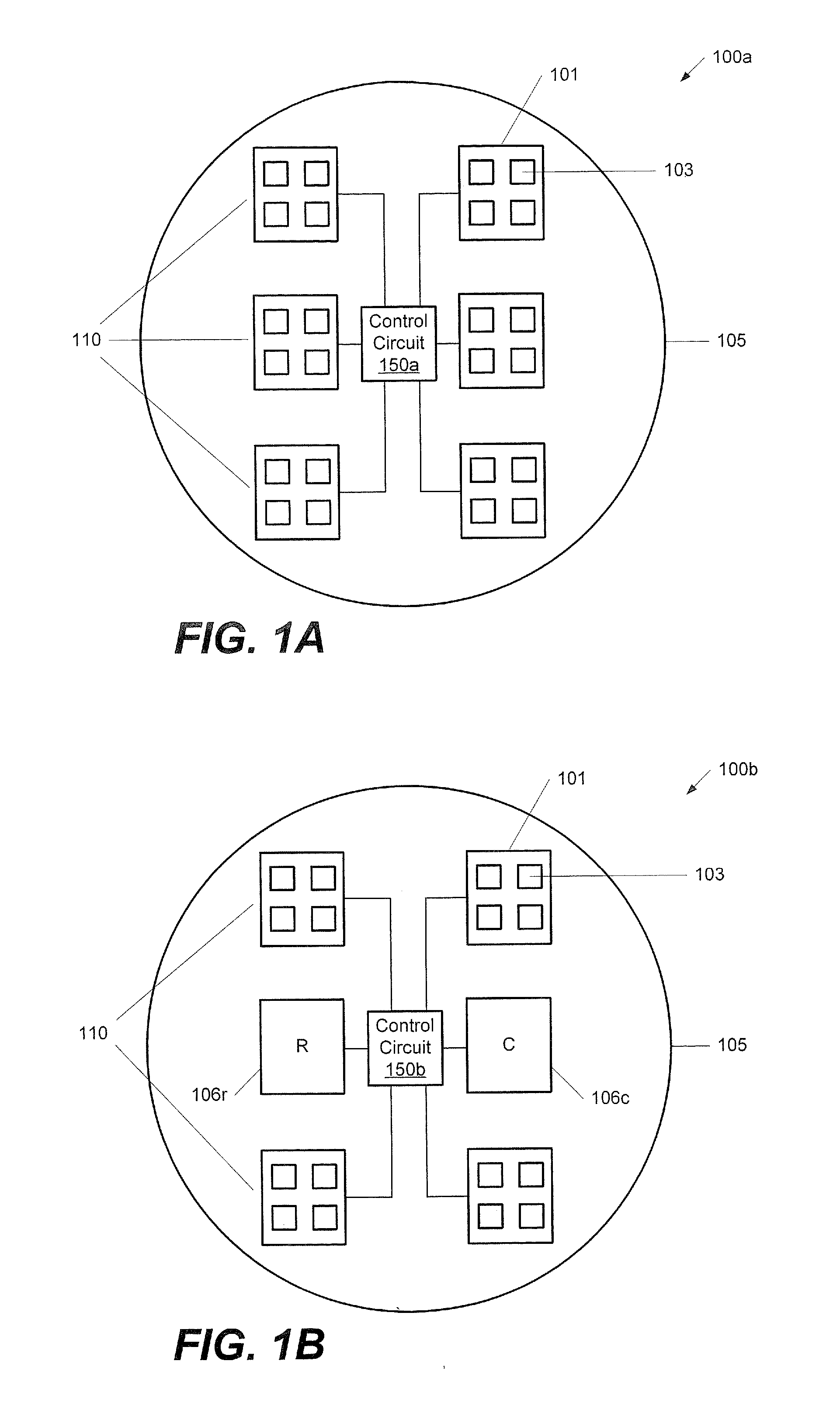
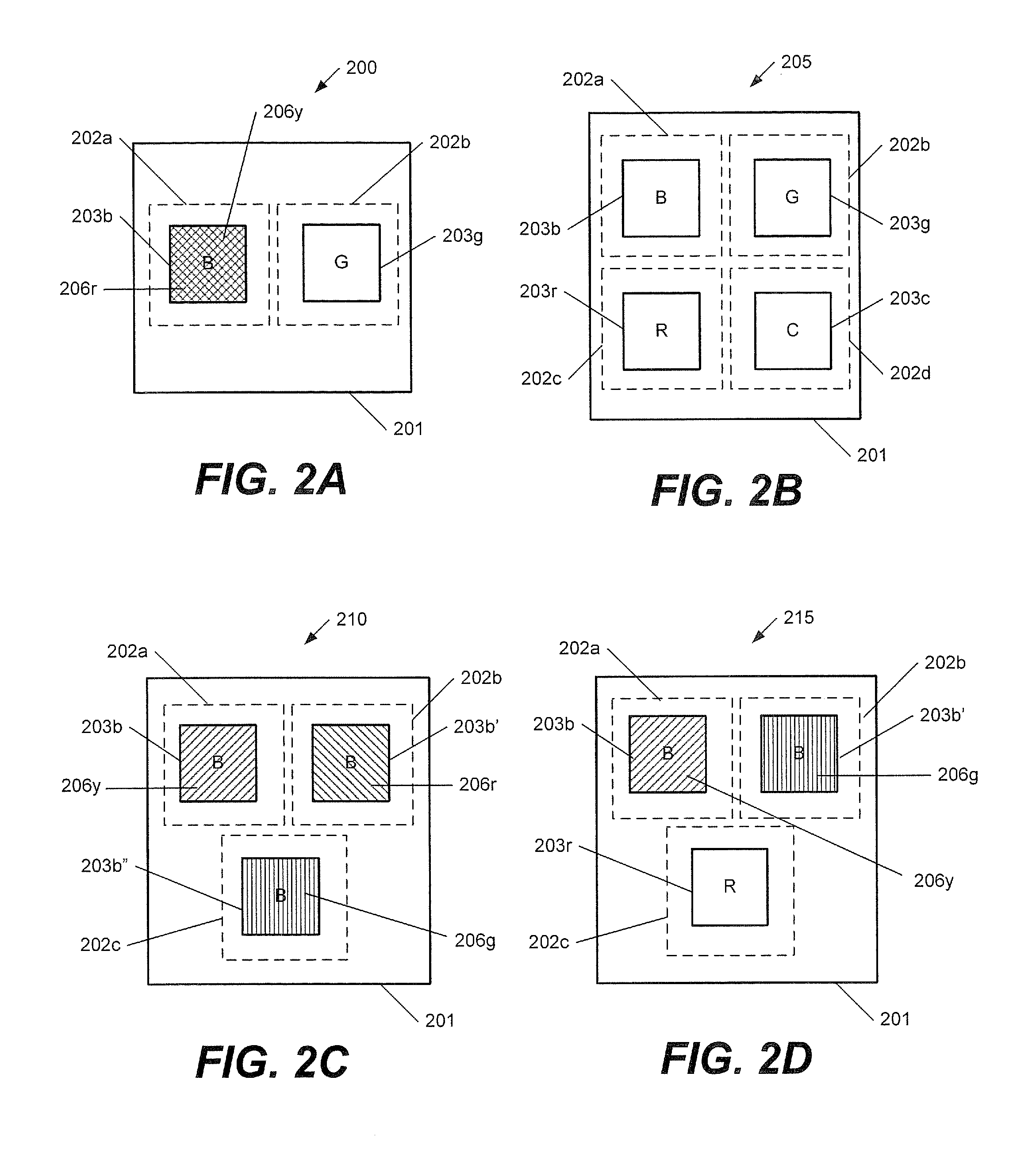
  • Multi-chip light emitting device lamps for providing high-cri warm white light and light fixtures including the same
  • Multi-chip light emitting device lamps for providing high-cri warm white light and light fixtures including the same
  • Multi-chip light emitting device lamps for providing high-cri warm white light and light fixtures including the same

Examples


Embodiment Construction

[0040] The present invention now will be described more fully with reference to the accompanying drawings, in which embodiments of the invention are shown. This invention may, however, be embodied in many different forms and should not be construed as limited to the embodiments set forth herein. Rather, these embodiments are provided so that this disclosure will be thorough and complete, and will fully convey the scope of the invention to those skilled in the art. In the drawings, the size and relative sizes of layers and regions may be exaggerated for clarity. Like numbers refer to like elements throughout.

[0041] It will be understood that when an element such as a layer, region or substrate is referred to as being “on” another element, it can be directly on the other element or intervening elements may also be present. It will be understood that if part of an element, such as a surface, is referred to as “inner,” it is farther from the outside of the device than other parts of th...


PUM


Abstract

A multi-chip lighting emitting device (LED) lamp for providing white light includes a submount including first and second die mounting regions thereon. A first LED chip is mounted on the first die mounting region, and a second LED chip is mounted on the second die mounting region. The LED lamp is configured to emit light having a spectral distribution including at least four different color peaks to provide the white light. For example, a first conversion material may at least partially cover the first LED chip, and may be configured to absorb at least some of the light of the first color and re-emit light of a third color. In addition, a second conversion material may at least partially cover the first and / or second LED chips, and may be configured to absorb at least some of the light of the first and / or second colors and re-emit light of a fourth color. Related light fixtures and methods are also discussed.

Description

CROSS-REFERENCE TO RELATED APPLICATIONS [0001] The present application is a continuation-in-part of and claims priority from U.S. patent application Ser. No. 11 / 032,363 filed Jan. 10, 2005, the disclosure of which is incorporated by reference herein in its entirety.FIELD OF THE INVENTION [0002] This invention relates to semiconductor light emitting devices, and more particularly, to multi-chip semiconductor light emitting devices including wavelength conversion materials and related devices. BACKGROUND OF THE INVENTION [0003] Light emitting diodes and laser diodes are well known solid state lighting elements capable of generating light upon application of a sufficient voltage. Light emitting diodes and laser diodes may be generally referred to as light emitting devices (“LEDs”). Light emitting devices generally include a p-n junction formed in an epitaxial layer grown on a substrate such as sapphire, silicon, silicon carbide, gallium arsenide and the like. The wavelength distributio...

Claims


Application Information

Patent Timeline
Patent Type & Authority Applications(United States)
IPC IPC(8): F21V9/00H01L29/06F21K99/00H01L33/00H01L33/48H01L33/50H01L33/58
CPCC09K11/586C09K11/623C09K11/7421C09K11/7702C09K11/7721H05B37/02F21K9/00H01L25/0753H01L33/504Y02B20/181C09K11/7734H01L2924/0002F21V23/005F21Y2105/12F21Y2105/10F21K9/64F21Y2115/10F21Y2113/17Y02B20/00H05B47/10H01L2924/00
Inventor MEDENDORP, NICHOLAS W. JR.MCCLEAR, MARKKELLER, BERND P.BRANDES, GEORGESLETOQUIN, RONAN P.
Owner CREELED INC
Learn More