Electrokinetic pump designs and drug delivery systems

a technology of electrokinetic pump and pump body, which is applied in the direction of pump, positive displacement liquid engine, machine/engine, etc., can solve the problems of difficulty and prohibitive time requirements for loading large volumes of delivery fluid using this techniqu

Inactive Publication Date: 2007-09-27
TELEFLEX LIFE SCI PTE LTD
View PDF7 Cites 23 Cited by
  • Summary
  • Abstract
  • Description
  • Claims
  • Application Information

AI Technical Summary

Benefits of technology

[0009] In another embodiment, there is provided a method for operating a fluid delivery system by inserting a piston assembly into a delivery chamber, the piston assembly having a pump housing, a piston head outside of the pump housing and attached to a shaft extending through a wall in the pump housing, a housing attached to the shaft and between electrodes in the pump housing; and filling the delivery chamber with a delivery fluid by withdrawing the piston head from within the delivery chamber. In one further aspect, the method fixes the position of the pump housing relative to the delivery chamber. In another aspect, there is provided the step of advancing the piston head in the delivery chamber by moving fluid in the pump chamber. In one aspect, moving fluid within the pump chamber comprises electrokineticly moving fluid through the housing. In another aspect, moving fluid within the pump chamber comprises providing an electric field between the electrodes. In yet another aspect, the filling step comprises withdrawing the pump assembly.

Problems solved by technology

These and other difficulties are encountered using conventional filling and pumping systems.
However, the time requirements for loading large volumes of delivery fluid using this technique may be prohibitive for time conscious applications and problematic for later pump operation.

Method used


Image

  • Electrokinetic pump designs and drug delivery systems
  • Electrokinetic pump designs and drug delivery systems
  • Electrokinetic pump designs and drug delivery systems

Examples


Embodiment Construction

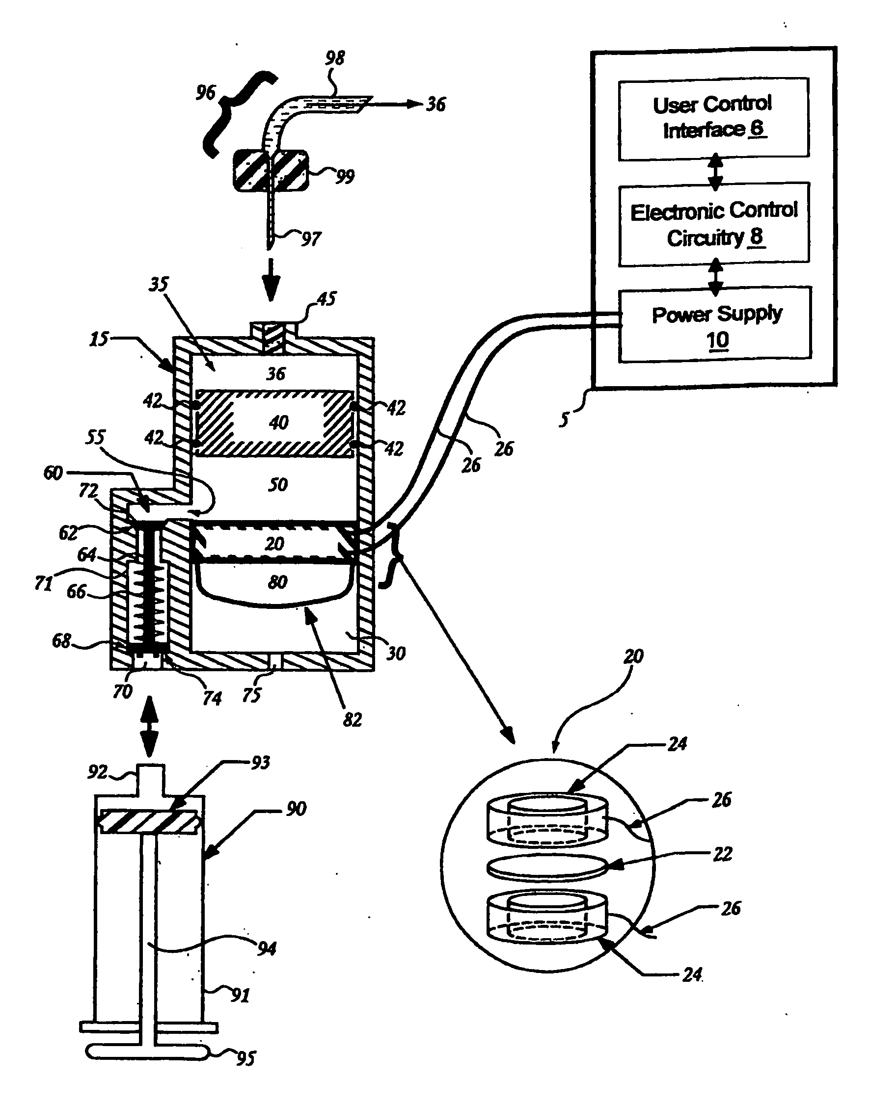
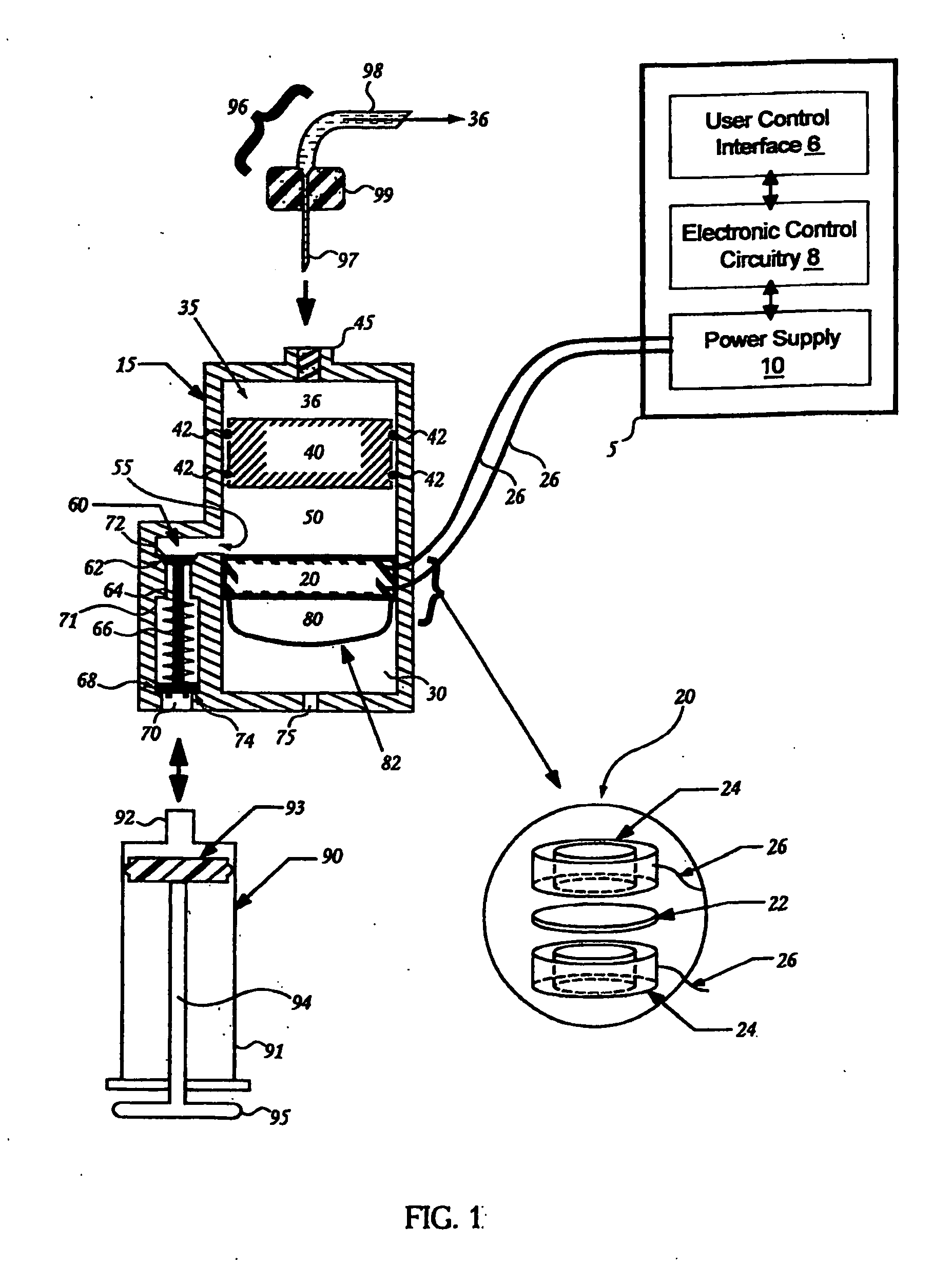
[0017]FIG. 1 will be described to provide an understanding of the basic components and operation of a typical fluid delivery system. FIG. 1 illustrates a cross section view of a fluid delivery system 1. The fluid delivery system has a first chamber 30, a second chamber 32 and a third chamber 35. A flow through pump element 20 (such as electrokinetic pump, as shown in FIG. 1) separates the first chamber 30 from the second chamber 32. A moveable pump element 40 (such as a floating piston, as shown) separates the second chamber 32 from the third chamber 35. While in this illustrative embodiment the moveable element 40 is a floating piston, any device that provides a moveable barrier may be used as will be illustrated in the examples that follow. In this embodiment, the first, the second and the third chambers are within a single housing 15. Seals 42 are used to seal the moveable pump element 40 as it moves within the housing 15. An outlet 45 provides communication between the third cha...


PUM


Abstract

One embodiment of the present invention provides a piston assembly having a piston housing filled with an electrolyte; a housing within the piston housing that divides the piston housing into a first portion and a second portion, the housing having apertures, a shaft connecting the housing to a piston head outside of the piston housing; and a porous material inside of the housing in contact with the electrolyte. Additionally, there are provided a method for filling the delivery chamber with a delivery fluid by withdrawing the piston head from within the delivery chamber. Yet another embodiment provides a method for filling a fluid delivery assembly by withdrawing a shaft from within the fluid delivery assembly to simultaneously displace a moving pump element within the delivery chamber and bypass fluid around a housing in the pump chamber.

Description

CROSS-REFERENCE TO RELATED APPLICATIONS [0001] This application claims the benefit of U.S. Provisional Application No. 60 / 739,390 filed Nov. 23, 2005, titled, “Electrokinetic Pump Designs and Drug Delivery Systems” which is incorporated herein by reference in its entirety. This application is related to the following co-pending patent applications: U.S. application Ser. No. (not yet assigned) filed herewith titled, “Electrokinetic Pump Designs and Drug Delivery Systems” (Attorney Docket number 10076-705.201); U.S. application Ser. No. 10 / 198,223, filed Jul. 17, 2002 titled, “Laminated Flow Devices”; U.S. application Ser. No. 10 / 273,723 filed Oct. 18, 2002 titled, “Electrokinetic Device Having Capacitive Electrodes”; U.S. application Ser. No. 10 / 322,083 filed Dec. 17, 2002 titled, “Electrokinetic Device Having Capacitive Electrodes” and U.S. application Ser. No. 11 / 112,867 filed Apr. 21, 2005 titled, “Electrokinetic Delivery Systems, Devices and Methods,” each of which are incorporat...

Claims


Application Information

Patent Timeline
Patent Type & Authority Applications(United States)
IPC IPC(8): F04B17/00
CPCA61M5/14526A61M2005/14513F04B19/04F04B17/00F04B19/006A61M2209/045Y10T137/0391
Inventor ANEX, DEONSCHWIMMER, CHARLESBLACK, DAVIDRUSH, RICHARDGEARHART, MICHAEL
Owner TELEFLEX LIFE SCI PTE LTD
Why Eureka
Try Eureka