

Insertion portion of an endoscope
a technology of endoscope and insertion portion, which is applied in the field of insertion portion of endoscope, can solve the problems of internal elements being damaged, metal helical tube may shrink, and easy damage, and achieve the effect of superior durability
- Summary
- Abstract
- Description
- Claims
- Application Information
AI Technical Summary
Benefits of technology
Problems solved by technology
Method used
Image

Examples
Embodiment Construction
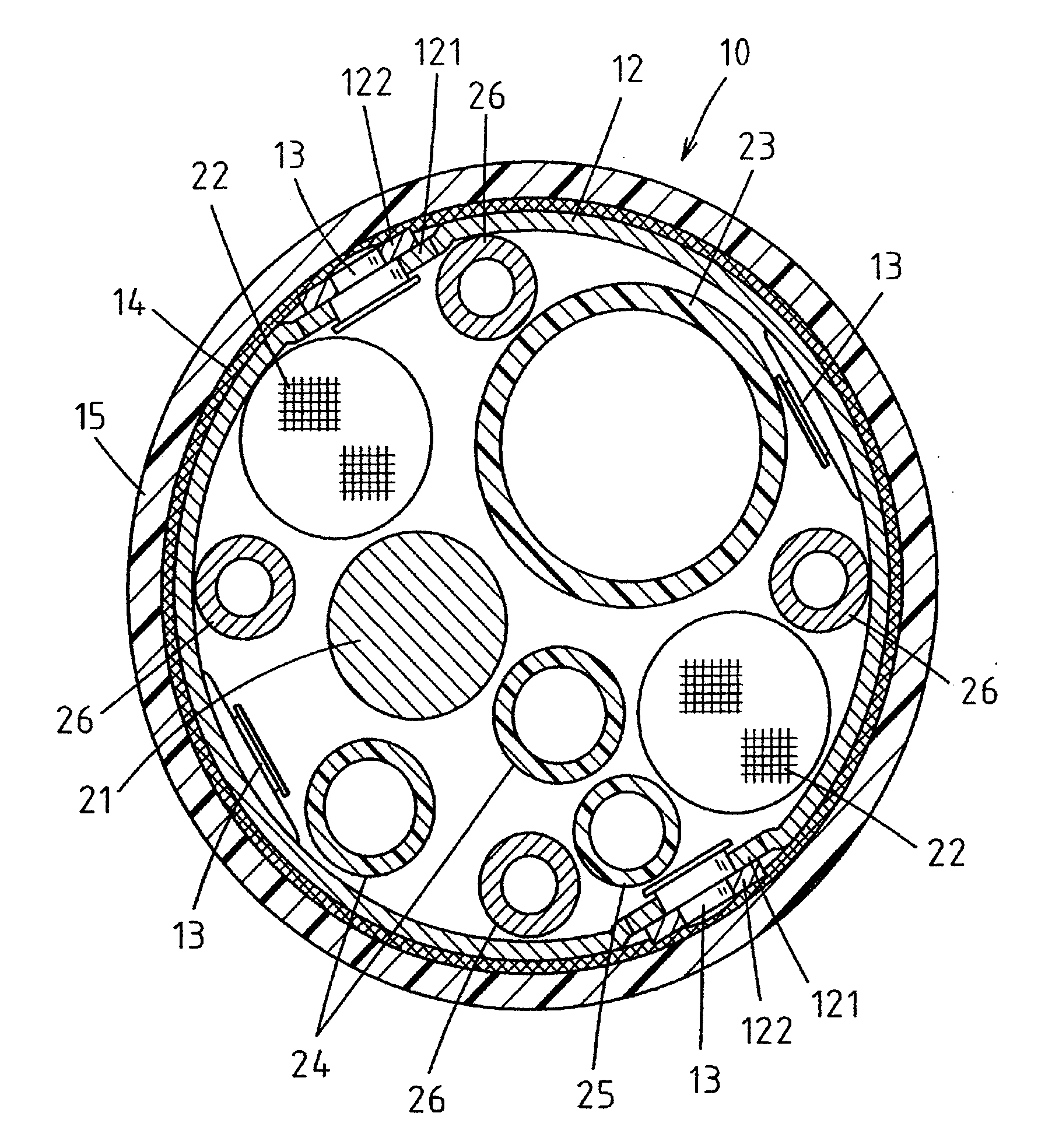
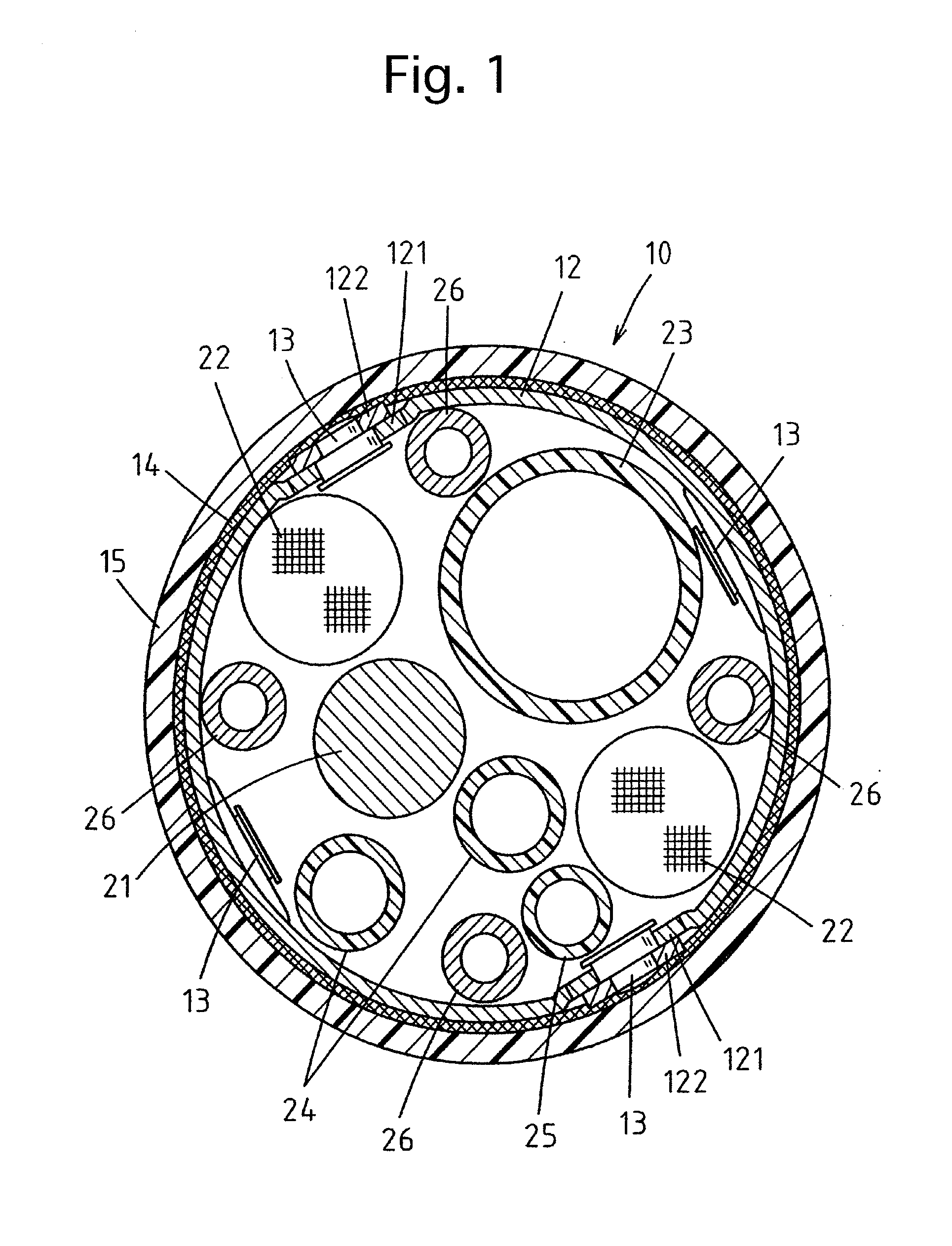
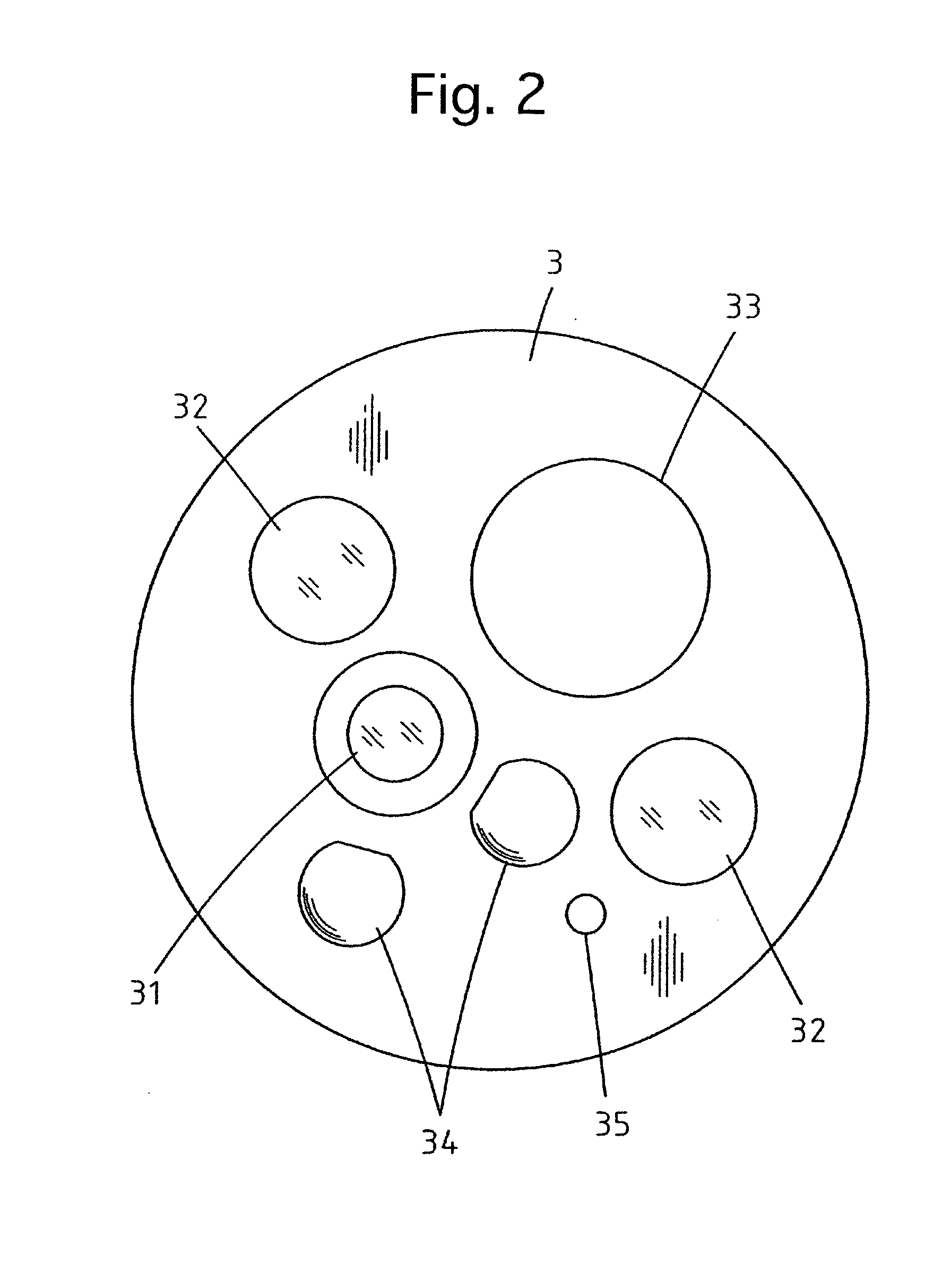
[0027]FIG. 3 shows the overall structure of the endoscope 1 according to the present invention. The endoscope 1 is provided with a control body 5 and an insertion portion connected to the control body 5. The distal end portion of the insertion portion is formed as a steerable bendable portion 2. The insertion portion of the endoscope 1 is provided with a flexible tubular portion 10, and the steerable bendable portion 2 is joined to the front end of the flexible tubular portion 10. The insertion portion of the endoscope 1 is further provided at the end of the steerable bendable portion 2 with an end body 3 in which an objective window 31, two illumination windows 32, a treatment tool exit mouth 33, two air / water supply nozzles 34 and a sub-water supply nozzle 35 are provided (see FIG. 2). The flexible tubular portion 10 and the steerable bendable portion 2 are connected to each other via a connecting ring 4. The steerable bendable portion 2 can be steered to bend freely (right, left,...
PUM
 Abstract
Description
Claims
Application Information