Insertion portion of an endoscope

a technology of endoscope and insertion portion, which is applied in the field of insertion portion of endoscope, can solve the problems of metal helical tube shrinkage, and achieve the effect of excellent durability and easy damage by bending

Inactive Publication Date: 2007-09-27
ASAHI KOGAKU KOGYO KK
View PDF5 Cites 59 Cited by
  • Summary
  • Abstract
  • Description
  • Claims
  • Application Information

AI Technical Summary

Benefits of technology

[0009]The present invention provides an insertion portion of an endoscope which uses a flexible tubular framework instead of a helical tube, wherein the flexible tubular framework is composed of a plurality of joint rings which are coupled in series via connecting shafts to be freely rotatable, and wherein one or more treatment tool insertion channels and one or more illumination optical fiber bundles among the various internal elements inserted into the flexible tubular framework to be installed therein, which easily damage by bending, can obtain excellent durability.
[0014]According to the present invention, the treatment tool insertion channel and the optical fiber bundle among various internal elements inserted into the flexible tubular framework to be installed therein, which are easily damaged by bending, are resistant to buckling and breaking, thus achieving excellent durability due to the configuration in which each of at least one treatment tool insertion channel and at least one optical fiber bundle is positioned at one of a position facing the inner end surface of one adjacent connecting shaft in the axial direction thereof and a position substantially facing the inner end surface of another adjacent connecting shaft in the insertion portion of the endoscope which uses a flexible tubular framework instead of a helical tube, wherein the flexible tubular framework is composed of a plurality of joint rings which are coupled in series via connecting shafts to be freely rotatable.

Problems solved by technology

However, in the case where the endoscope is sterilized by a process of steaming under pressure (autoclaving), the metal helical tube may shrink.

Method used


Image

  • Insertion portion of an endoscope
  • Insertion portion of an endoscope
  • Insertion portion of an endoscope

Examples


Embodiment Construction

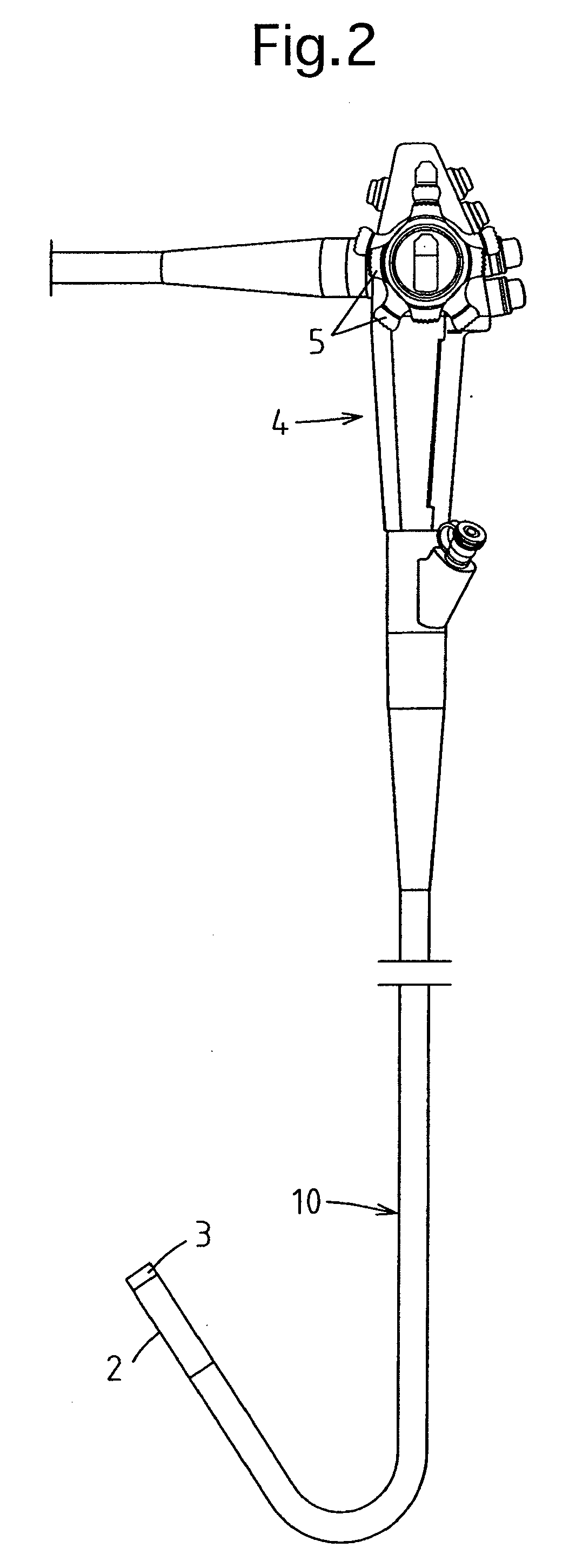
[0022]FIG. 2 shows the overall structure of an endoscope 1 according to the present invention. The endoscope 1 is provided with a control body 4 and an insertion portion connected to the control body 4. The distal end portion of the insertion portion is formed as a steerable bendable portion 2. The insertion portion of the endoscope 1 is provided with a flexible tubular portion 10, and the steerable bendable portion 2 is joined to the front end of the flexible tubular portion 10. The insertion portion of the endoscope 1 is further provided at the front end of the steerable bendable portion 2 with an end body 3 in which an objective window (not shown) and other openings / nozzles are provided. The steerable bendable portion 2 can be steered to bend freely (right, left, upward and downward) by controlling steering knobs 5 provided on the control body 4.

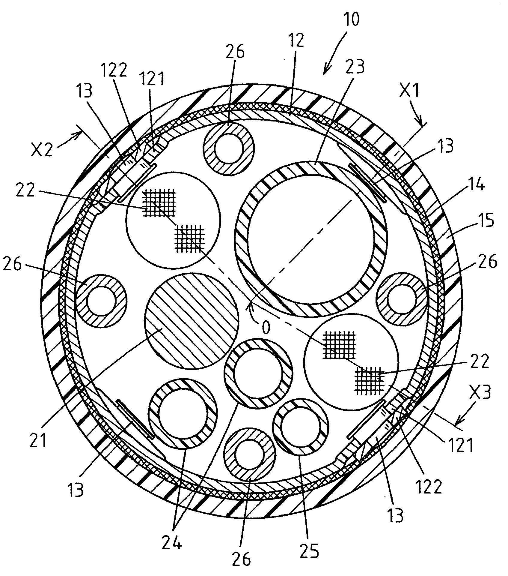
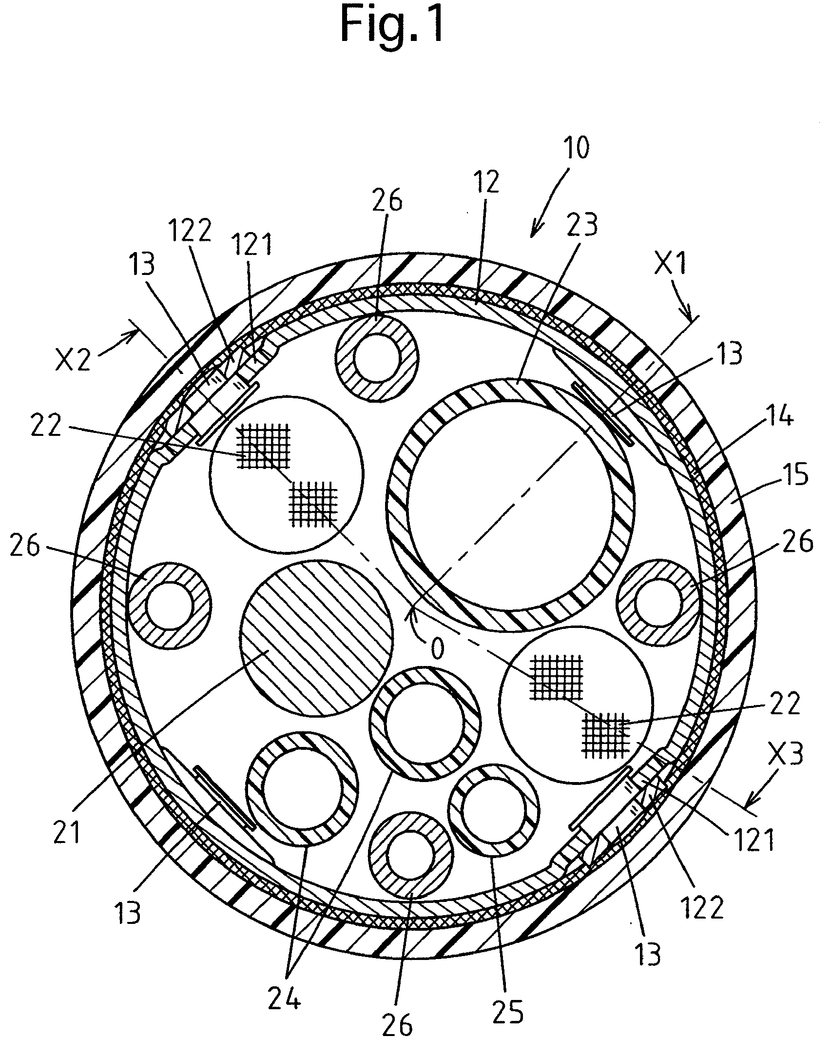
[0023]FIG. 3 shows the flexible tubular portion 10. The flexible tubular portion 10 in this embodiment of the endoscope is provided with...


PUM


Abstract

An insertion portion of an endoscope includes a flexible tubular framework composed of short-cylindrical joint rings coupled in series via rotatable connecting shafts; and flexible internal elements including a treatment tool insertion channel and a optical fiber bundle(s). Each short-cylindrical joint ring is coupled at one end to one adjacent joint ring via two connecting shafts at 180-degree symmetrical positions and is coupled at the other end to another adjacent joint ring via another two connecting shafts at 180-degree symmetrical positions with a 90-degree phase shift with respect to the one adjacent joint ring. Inner end surfaces of one set of connecting shafts at a specific circumferential position are arranged to face the treatment tool insertion channel, and inner end surfaces of another set of the connecting shafts at another specific circumferential direction are arranged to face or substantially face the optical fiber bundle.

Description

BACKGROUND OF THE INVENTION[0001]1. Field of the Invention[0002]The present invention relates to an insertion portion of an endoscope.[0003]2. Description of the Related Art[0004]An insertion portion of an endoscope which is introduced into a body is generally constructed of a metal helical tube, a mesh tube and a flexible jacket, wherein the metal helical tube is sheathed with the mesh tube and further sheathed with the flexible jacket. However, in the case where the endoscope is sterilized by a process of steaming under pressure (autoclaving), the metal helical tube may shrink. Accordingly, to achieve durability against autoclaving, the helical tube may be replaced by a flexible tubular framework consisting of a plurality of short-cylindrical joint rings which are coupled in series via connecting shafts to be freely rotatable (as shown in, e.g., Japanese unexamined patent publication H09-24020).[0005]In the aforementioned flexible tubular framework that is used as a replacement fo...

Claims


Application Information

Patent Timeline
Patent Type & Authority Applications(United States)
IPC IPC(8): A61B1/00
CPCA61B1/0055G02B23/2476A61B1/07A61B1/015
Inventor OGINO, TAKAYUKI
Owner ASAHI KOGAKU KOGYO KK
Why Eureka
Try Eureka