Navigation apparatus

Inactive Publication Date: 2007-09-27
DENSO CORP
View PDF18 Cites 35 Cited by
  • Summary
  • Abstract
  • Description
  • Claims
  • Application Information

AI Technical Summary

Benefits of technology

[0008]It is an object of the present invention to provide a navigation apparatus solving the above problems or the like. In this navigation apparatus, a predetermined

Problems solved by technology

The anti-theft system in Patent document 1 is useful in preventing stealing a vehicle itself but useless in stealing a navigation apparatus.
However, when the navi

Method used


Image

  • Navigation apparatus
  • Navigation apparatus
  • Navigation apparatus

Examples


first embodiment

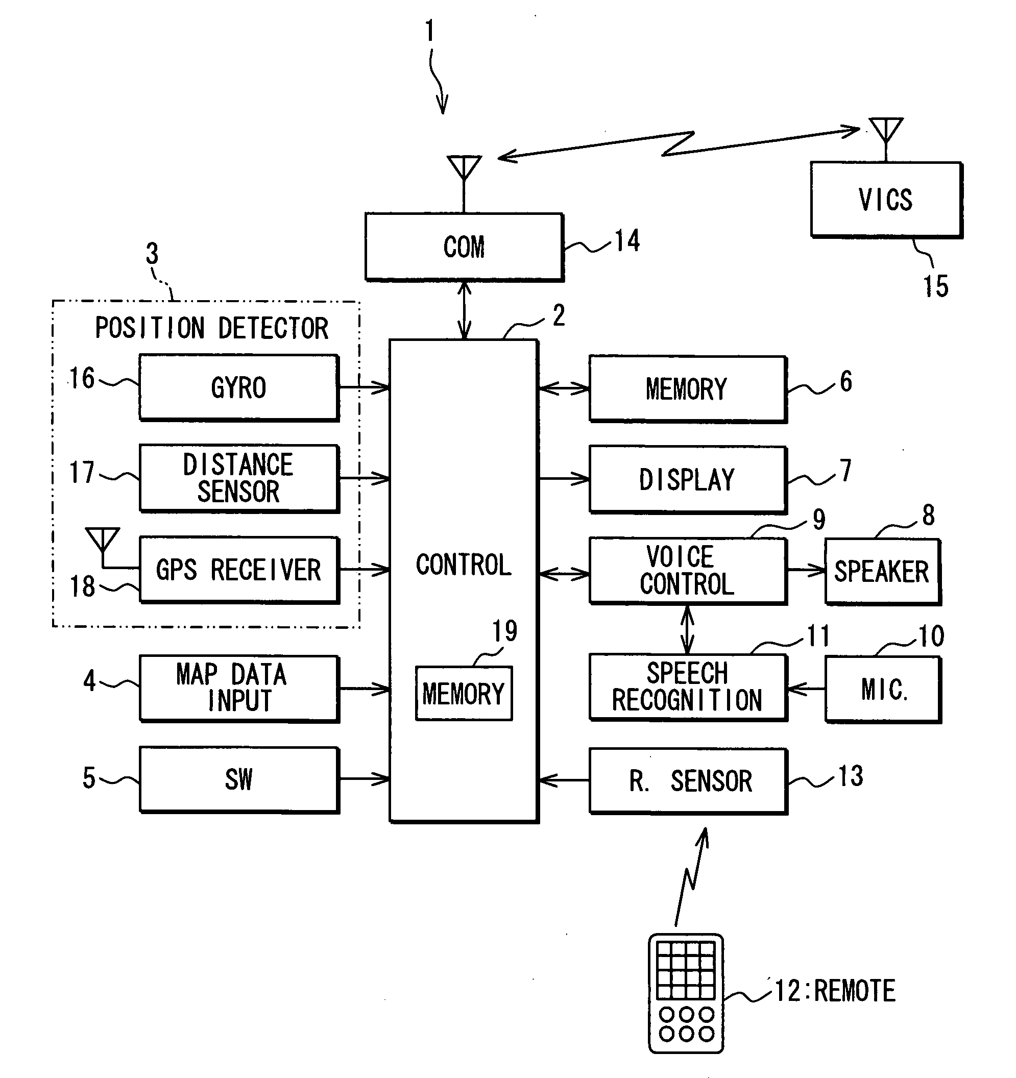
[0020]A navigation apparatus 1 mounted in a subject vehicle will be explained below as an embodiment of the present invention. As shown in FIG. 1, the navigation apparatus 1 includes a control unit 2 mainly having a micro-computer; a position detector 3 detecting a current position of the vehicle; a map data input unit 4, an operation switch group 5; an external memory device 6; a display unit 7 having liquid crystal color display; a voice controller 9 connected with a speaker 8; a speech recognition unit 11 recognizing speeches from a microphone 10; a remote sensor 13 communicating commands or the like with a remote 12; and a communications unit 14 as an external information input / output unit to perform data communications by wireless with an outside information center 15 (e.g., VICS (Vehicle Information and Communication System) center (Trademark)).

[0021]The position detector 3 includes a gyro scope 16 detecting a vehicle's rotational angular speed; a distance sensor 17 detecting ...

second embodiment

[0045]FIG. 4 is similar to FIG. 2 to illustrate a function control process performed by the control unit 2 in a second embodiment when the navigation apparatus 1 is supplied with the power from an in-vehicle battery. Steps in FIG. 4 identical to those in FIG. 2 are assigned the same step numbers. Step S11, Step S12, Step S13 are new steps included in the process in the second embodiment. The control unit 2 of the second embodiment does not invalidate the predetermined function until a predetermined grace period elapses from the start-up; therefore, the navigation apparatus 1 continues the normal operation during the grace period.

[0046]Just after Step S2 is performed, the control unit 2 does not perform Step S3 for invalidating the function but, alternatively, Step S11 for starting a timer (i.e., starting counting of the timer) to count the grace period (e.g., tem minutes). Then, when both the determinations at Step S4 and Step S6 are negated (i.e., when the vehicle has not traveled ...

third embodiment

[0049]FIG. 5 is similar to FIG. 2 to illustrate a function control process performed by the control unit 2 in a third embodiment when the navigation apparatus 1 is supplied with the power from an in-vehicle battery. Steps in FIG. 5 identical to those in FIG. 2 are assigned the same step numbers. Steps S21, S22, S23, S24 are new steps included in the process in the third embodiment. The control unit 2 of the third embodiment does not invalidate the predetermined function until a predetermined permission period elapses from when the vehicle travels through the invalidating route or invalidating point, irrespective of whether the navigation apparatus 1 is started up or not; therefore, the navigation apparatus 1 continues the normal operation during the permission period.

[0050]Before the determination for the start-up at Steps S1, S2, the control unit 2 determines whether a timer for counting the permission period is operating (Step S21). When the timer is determined not to be operating...


PUM


Abstract

In a navigation apparatus in a vehicle, a user designates a validating route, which is stored in a memory device. A control unit invalidates a predetermined function of the navigation apparatus at a start-up, which is for the first time after an in-vehicle battery is connected or which results from turning on of a power source. Use of the navigation apparatus by the user is thereby disturbed. When the control unit determines that a route, which the vehicle has traveled through, is included in the previously designated validating route stored in the memory device, the control unit re-validates the invalidated predetermined function.

Description

CROSS REFERENCE TO RELATED APPLICATION[0001]This application is based on and incorporates herein by reference Japanese Patent Application No. 2006-82842 filed on Mar. 24, 2006.FIELD OF THE INVENTION[0002]The present invention relates to a navigation apparatus having an anti-theft function.BACKGROUND OF THE INVENTION[0003]Stealing a vehicle or a navigation apparatus mounted in a vehicle has been increasing. To prevent stealing of a vehicle, Patent document 1 discloses an anti-theft system. In the system, it is monitored whether the vehicle departs from a designated travel route by a predetermined distance. When the vehicle has departed, an operator is given an alarm against departing from the travel route. When the alarm is not released, an emergency warning is generated and information on theft including vehicle's positional information is transmitted to an information center or security company.[0004]To prevent stealing of a navigation apparatus from a vehicle, Patent document 2 di...

Claims


Application Information

Patent Timeline
IPC IPC(8): G01C21/00B60R11/02B60R25/102B60R25/23B60R25/30B60R25/33G01C21/26G08B13/00G08G1/0969G09B29/00G09B29/10
CPCG01C21/00B60R25/33
Inventor SAKANO, HIROKAZU
Owner DENSO CORP
Why Eureka
Try Eureka