Gutter cleaning vacuum system including a novel hinged vacuum manifold assembly

a vacuum system and gutter cleaning technology, applied in the direction of cleaning filter means, colloidal chemistry, cleaning equipment, etc., can solve the problems of large volume, large vacuum system, bulky design, etc., and achieve the effect of reducing cleanup time, convenient collection and storage, and sufficient power

Inactive Publication Date: 2007-10-04
MCINTIRE PAUL CURTIS
View PDF11 Cites 11 Cited by
  • Summary
  • Abstract
  • Description
  • Claims
  • Application Information

AI Technical Summary

Benefits of technology

[0010] In various exemplary embodiments, the present invention provides a lightweight, maneuverable, thin-walled, transparent apparatus for use with a heavy-duty vacuum system for quickly and easily collecting and storing large volumes of bulky debris, thereby reducing the time needed for cleanup. The present invention also provides an improved vacuum manifold assembly that may be used in conjunction with various gas and electric blower/vacuum motors, both novel and conventional. The present inv...

Problems solved by technology

One disadvantage of this type of industrial/commercial vacuum system is its large, bulky design.
Vacuum systems of such designs are comparatively heavy due to the metal cylinder which forms the receptacle for debris.
Due to their bulk and weight, such vacuum systems may be difficult to maneuver over large areas, such as factory floors, lumber yards, construction sites, amusement parks, convention halls, shopping centers, residences, and the like.
Likewise, such vacuum systems may be difficult to maneuver outdoors in gutter cleaning applications.
Further, such vacuum systems that use suction (water-lift) to clean, typically have only 60-80 CFM (approximately 1700-2265 liters/minute) of air flow, and typically use a maximum two-inch (approximately 5-centimeter) diameter intake hose that limits the size of the material collected.
Thus, there is a loss of power when the vacuum intake is extended beyond a few feet (meters) from the unit.
Anoth...

Method used


Image

  • Gutter cleaning vacuum system including a novel hinged vacuum manifold assembly
  • Gutter cleaning vacuum system including a novel hinged vacuum manifold assembly
  • Gutter cleaning vacuum system including a novel hinged vacuum manifold assembly

Examples


Embodiment Construction

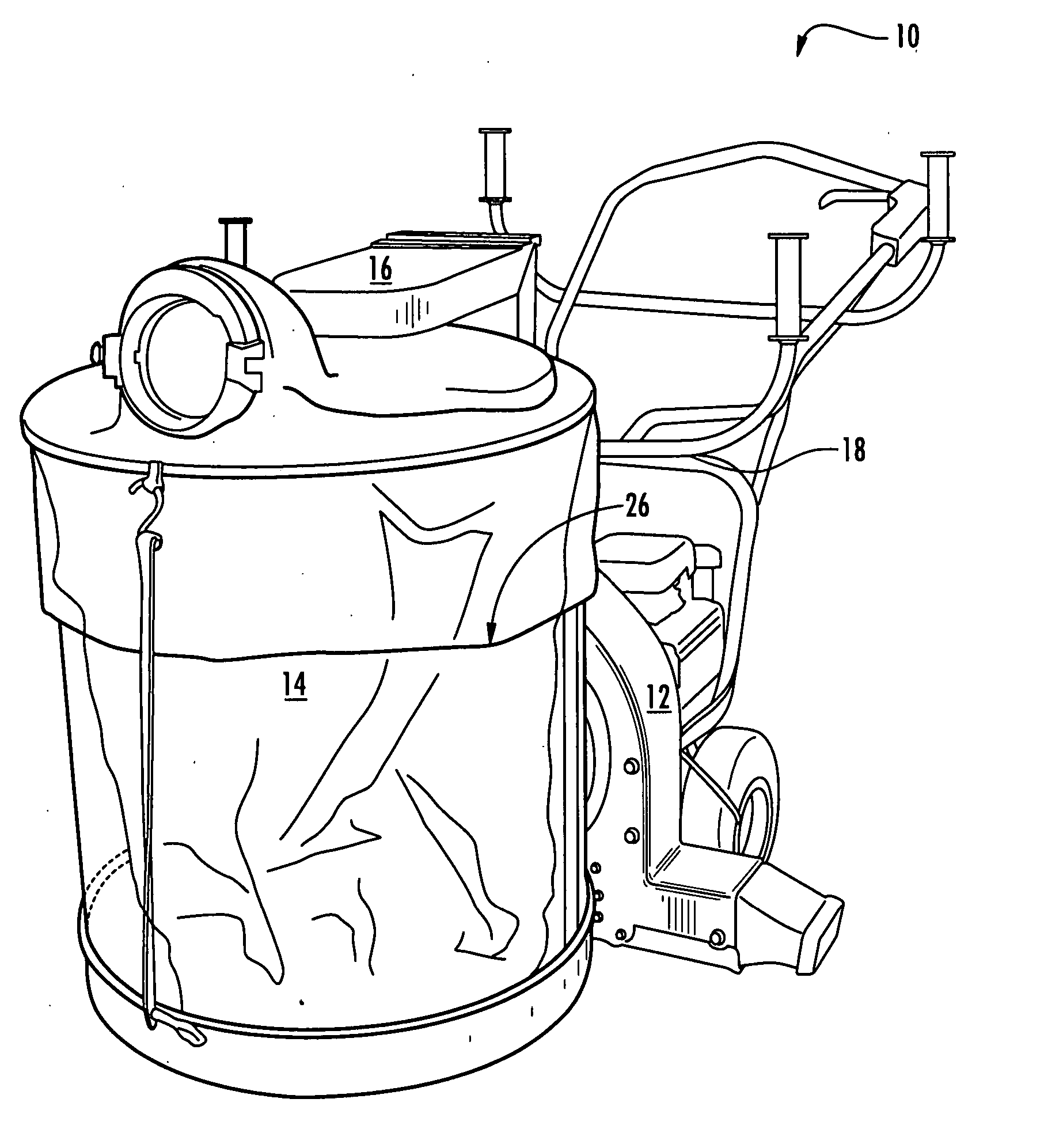
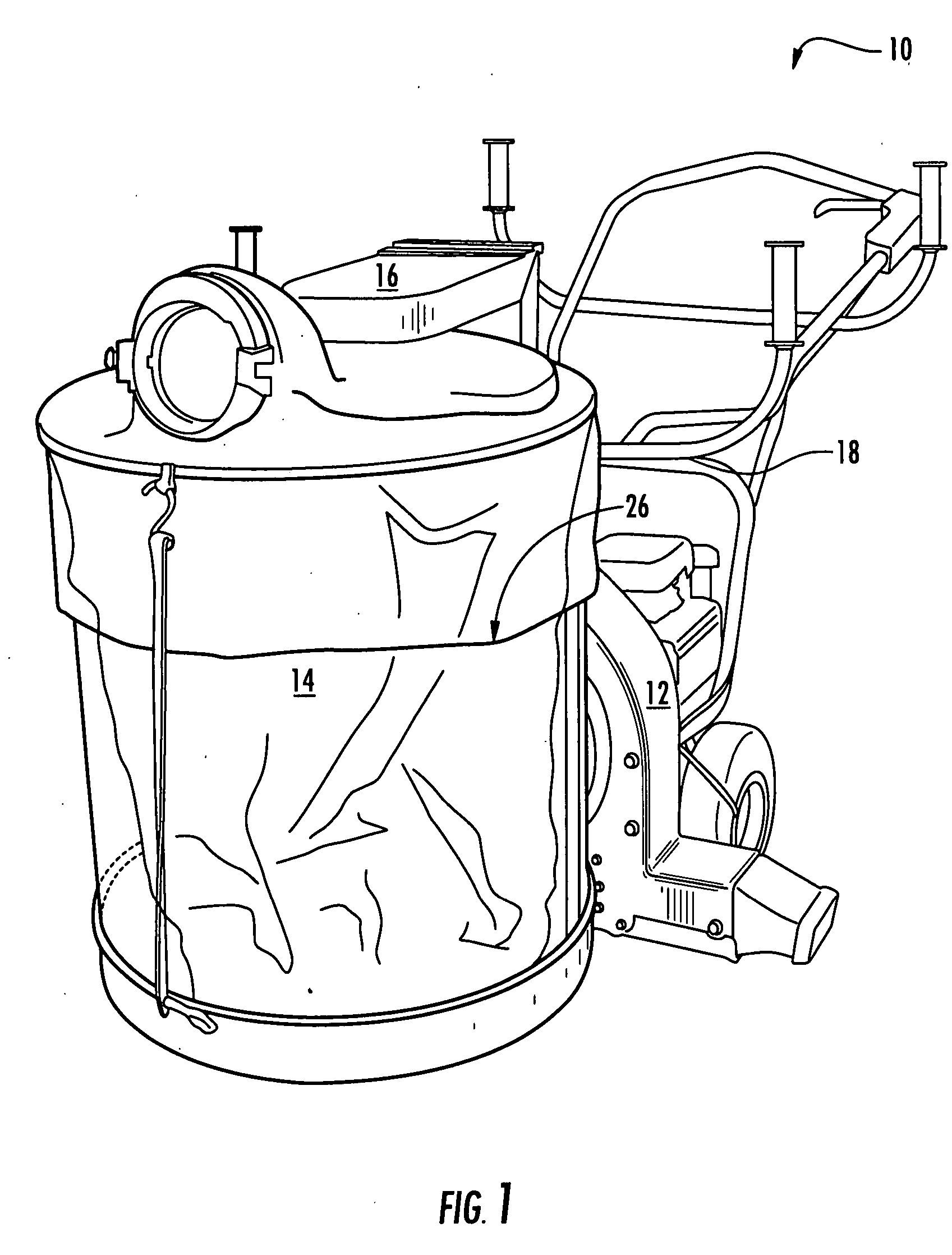
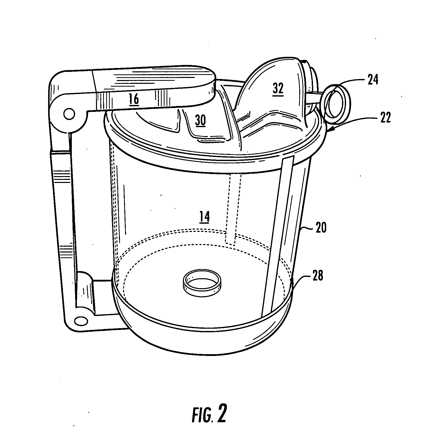
[0034] In various exemplary embodiments, the present invention provides a lightweight, maneuverable, thin-walled, transparent apparatus for use with a heavy-duty vacuum system for quickly and easily collecting and storing large volumes of bulky debris, thereby reducing the time needed for cleanup. The present invention also provides an improved vacuum manifold assembly that may be used in conjunction with various gas and electric blower / vacuum motors, both novel and conventional. The present invention further provides various gutter cleaning and other tools that may be used in conjunction with such a vacuum system. The gutter cleaning vacuum system including the improved hinged vacuum manifold assembly of the present invention has sufficient power and is designed such that the various gutter cleaning and other tools are effective, suction-wise, at great distances from the unit, such that an operator may use the gutter cleaning and other tools at great distances over his / her head, fo...


PUM


Abstract

In various exemplary embodiments, the present invention provides a lightweight, maneuverable, thin-walled, transparent apparatus for use with a heavy-duty vacuum system for quickly and easily collecting and storing large volumes of bulky debris, thereby reducing the time needed for cleanup. The present invention also provides an improved vacuum manifold assembly that may be used in conjunction with various gas and electric blower/vacuum motors, both novel and conventional. The present invention further provides various gutter cleaning and other tools that may be used in conjunction with such a vacuum system. The gutter cleaning vacuum system including the improved hinged vacuum manifold assembly of the present invention has sufficient power and is designed such that the various gutter cleaning and other tools are effective, suction-wise, at great distances from the unit, such that an operator may use the gutter cleaning and other tools at great distances over his/her head, for example.

Description

CROSS-REFERENCE TO RELATED APPLICATION(S) [0001] The present non-provisional patent application claims the benefit of priority of U.S. Provisional Patent Application No. 60 / 784,247, filed on 21 Mar. 2006, and entitled “GUTTER CLEANING VACUUM SYSTEM INCLUDING A NOVEL HINGED VACUUM MANIFOLD ASSEMBLY,” the contents of which are incorporated in full by reference herein.FIELD OF THE INVENTION [0002] The present invention relates generally to the vacuum system and gutter cleaning fields, among others. More specifically, the present invention relates to a gutter cleaning vacuum system including a novel hinged vacuum manifold assembly. This gutter cleaning vacuum system including a novel hinged vacuum manifold assembly may be used in conjunction with various gas and electric blower / vacuum motors, both novel and conventional, and with various gutter cleaning and other tools, both novel and conventional. Advantageously, the gutter cleaning vacuum system including a novel hinged vacuum manifol...

Claims


Application Information

Patent Timeline
IPC IPC(8): A47L9/00
CPCA47L5/365E04D13/0765A47L9/1418A47L9/009Y10S55/03
Inventor MCINTYRE, PAUL CURTIS
Owner MCINTIRE PAUL CURTIS
Why Eureka
Try Eureka