Sewing machine and spool pin stand therefor

a technology of spool pins and sewing machines, which is applied in the field of sewing machines, can solve the problems of easy misselection of thread passages, operator's inability to clearly determine to which spool pin the thread spool should be attached, and operator's inability to attach thread spools to erroneous spool pins

Active Publication Date: 2007-10-04
BROTHER KOGYO KK
View PDF8 Cites 10 Cited by
  • Summary
  • Abstract
  • Description
  • Claims
  • Application Information

AI Technical Summary

Benefits of technology

[0013]According to the above-described construction, a plurality of the thread color display units are provided on the spool pin stand for displaying the thread colors in the color-variable manner so that the thread colors correspond to the spool pins. Consequently, the operator can easily but exactly attach a thread spool having the same thread color as displayed on the display unit to the spool pin for which the thread color is displayed, without erroneously selecting another spool pin.

Problems solved by technology

As a result, there is a problem that the threading passage is easily mis-selected.
Accordingly, the operator cannot clearly determine to which spool pin the thread spool should be attached even though he or she can understand a passage along which the needle thread is passed.
Consequently, there is a possibility that the operator may attach a thread spool to an erroneous spool pin.
In this case, the needle thread cannot be drawn from the thread spool smoothly such that sewing cannot be carried out normally.

Method used


Image

  • Sewing machine and spool pin stand therefor
  • Sewing machine and spool pin stand therefor
  • Sewing machine and spool pin stand therefor

Examples


Embodiment Construction

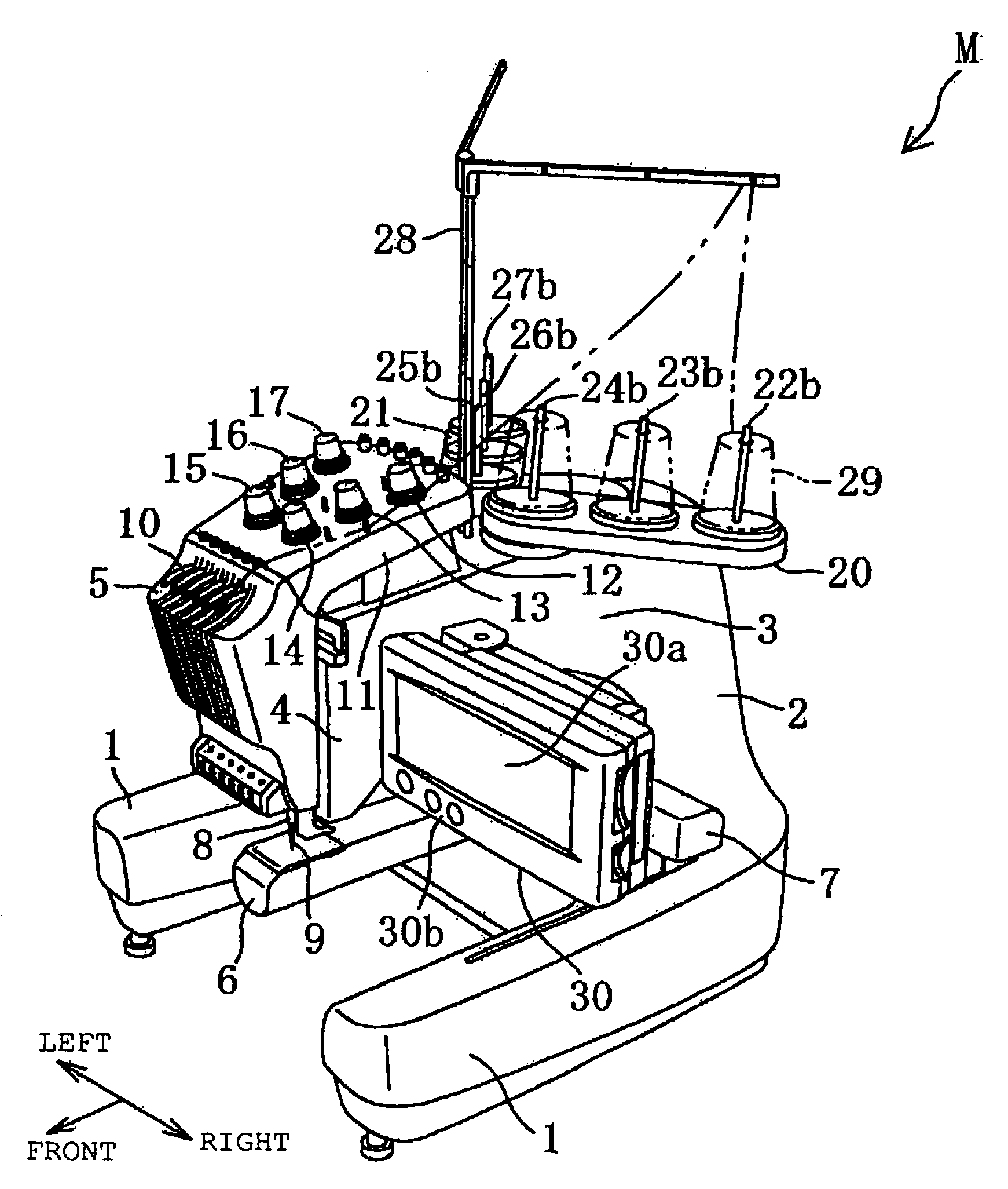
[0027]One illustrative example of the present disclosure will be described with reference to FIGS. 1 to 10. Referring to FIG. 1, a multineedle embroidery sewing machine M of the example is shown. The multineedle embroidery sewing machine M comprises a pair of right and left support legs 1, a pillar 2 standing on rear ends of the support legs 1 and an arm 3 extending frontward from an upper part of the pillar 2. The multineedle embroidery sewing machine M further comprises a cylinder bed 6 extending frontward from a lower end of the pillar 2, a carriage driving mechanism (not shown) moving an embroidery frame (not shown) via a carriage 7 in the X direction (a right-left direction) and the Y direction (a front-rear direction) perpendicular to the X direction and a threading mechanism (not shown) passing a thread through a needle eye of a sewing needle 9 as will be described later. Since each of the carriage driving mechanism and the threading mechanism has an ordinary construction, th...


PUM


Abstract

A sewing machine includes needlebars for a sewing operation using a plurality of needle threads, a spool pin stand having a plurality of spool pins to which thread spools corresponding to the needlebars are attachable, respectively, thread passage defining members located on a thread passage extending from the spool pin stand to the needlebars, a storage unit storing sewing data including at least thread color information about colors of the needle threads, thread supply display units located on the spool pin stand so as to correspond to the spool pins respectively, the thread supply display units displaying the thread colors in a color-variable manner, respectively, and a thread color information display control unit controlling the thread supply display units based on the thread color information read from the sewing data storage unit, so that thread colors corresponding to the spool pins are displayed by the thread supply display units, respectively.

Description

CROSS-REFERENCE TO RELATED APPLICATIONS[0001]This application is based upon and claims the benefit of priority from the prior Japanese Patent Application No. 2006-101561 filed on Apr. 3, 2006, the entire contents of which are incorporated herein by reference.BACKGROUND[0002]1. Technical Field[0003]The present disclosure relates to a sewing machine provided with a spool pin stand on which a display device is mounted for displaying a color of needle thread used for sewing.[0004]2. Description of the Related Art[0005]Multineedle sewing machines have conventionally been put to practical use in order that colorful embroidery patterns may be sewn using embroidery threads of a plurality of colors. One of the multineedle sewing machines comprises a spool pin stand having a plurality of spool pins to which thread spools are attachable respectively and a needlebar mechanism including a plurality of, for example, six, nine or twelve needlebars which are aligned and have lower ends to which sew...

Claims


Application Information

Patent Timeline
Patent Type & Authority Applications(United States)
IPC IPC(8): D05B23/00
CPCB65H49/04B65H2551/20D05D2205/16D05B43/00D05B79/00B65H2701/31
Inventor NOMURA, YUTAKASUZUKI, HIROYUKINOGUCHI, CHIKAHISAJIMBO, MASARUITO, EIICHI
Owner BROTHER KOGYO KK
Why Eureka
Try Eureka