

Suction catheter for endotube and methods of manufacture and operation thereof
- Summary
- Abstract
- Description
- Claims
- Application Information
AI Technical Summary
Benefits of technology
Problems solved by technology
Method used
Image

Examples
Embodiment Construction
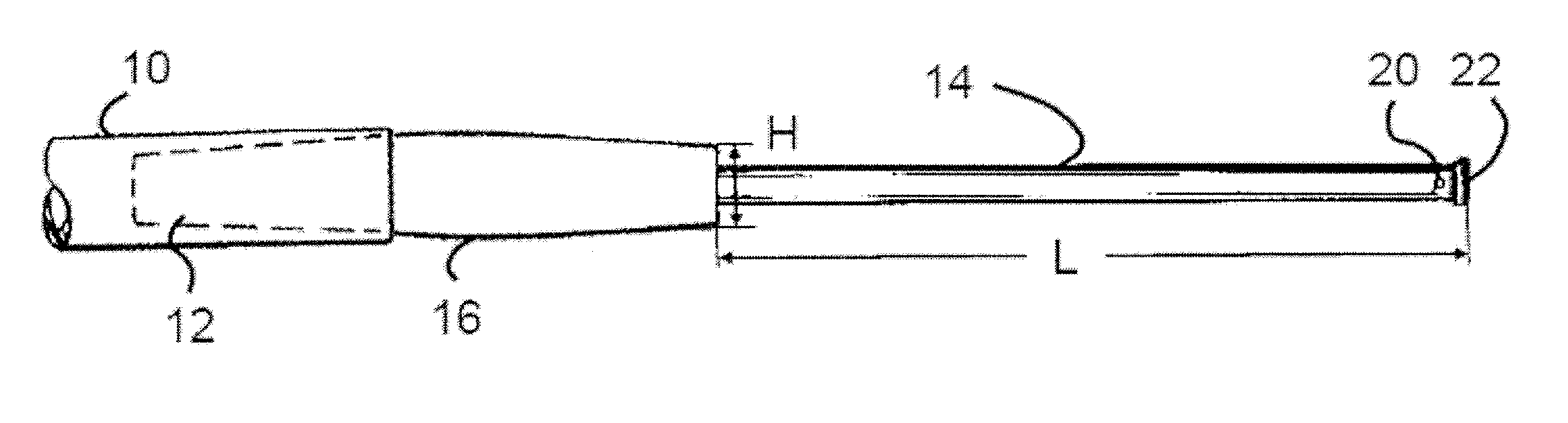
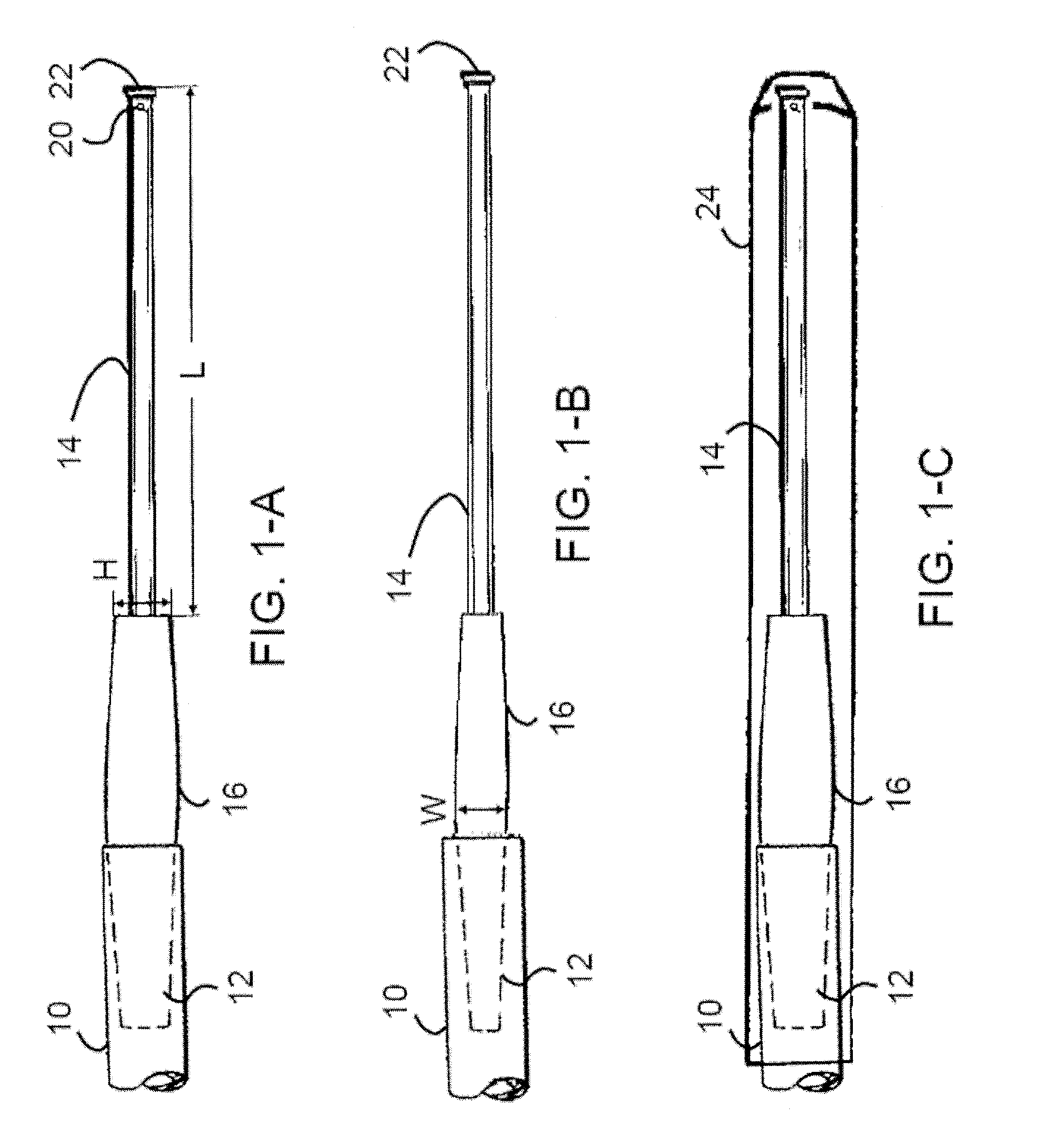
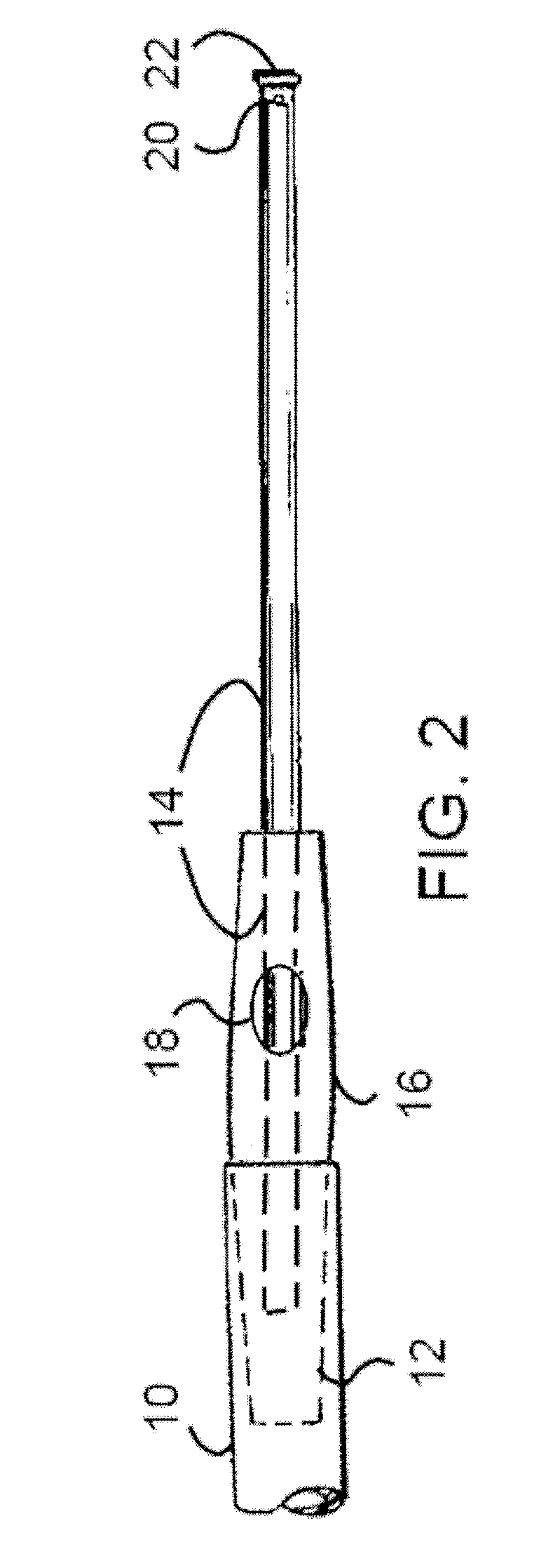
[0038] In certain embodiments, the present invention provides a tracheal tube length suction catheter that can be used to quickly and easily aspirate secretions from tracheostomy and endotracheal tubes. After each use the catheter can be safely stored in a clean encasement that slips over the catheter and grips to the outside of the connection tubing.
[0039] While animal studies clearly demonstrate denuded epithelium and inflammation where suctioning past the tracheal tube is routinely performed, the majority of clinicians often still deep-suction their patients. Abandoning the practice has been advocated for more than a decade, though with little change in routine. By providing a length-adjustable catheter or sizing a family of catheters to match the length of tracheal tubes, as described herein, the clinician is physically unable to suction past the end of the tracheal tube and injury to the airway will be prevented.
[0040] In certain embodiments of the present invention, the suct...
PUM
 Abstract
Description
Claims
Application Information