Liquid Filling Nozzle

Inactive Publication Date: 2007-10-04
KAO CORP
View PDF7 Cites 32 Cited by
  • Summary
  • Abstract
  • Description
  • Claims
  • Application Information

AI Technical Summary

Benefits of technology

[0004] Objects of the present invention are to make liquid flow

Problems solved by technology

Such liquid accumulation causes liquid dripping as the liquid spa

Method used


Image

  • Liquid Filling Nozzle
  • Liquid Filling Nozzle
  • Liquid Filling Nozzle

Examples


embodiment 1 figs.1 to 5

Embodiment 1 FIGS. 1 to 5, FIG. 9

[0021] In a liquid filling device 10, as shown in FIGS. 4(A), 4(B), 5(A), and 5(B), a switching valve 14 of a pump 15 is connected to a liquid filling head 11 including a filling nozzle 12 and a discharge valve 13. A liquid feed pipe16 is also connected to the switching valve 14.

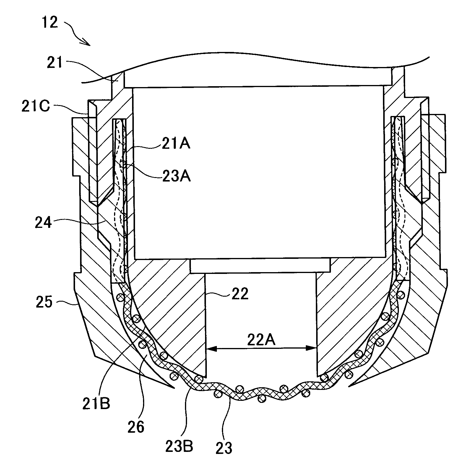
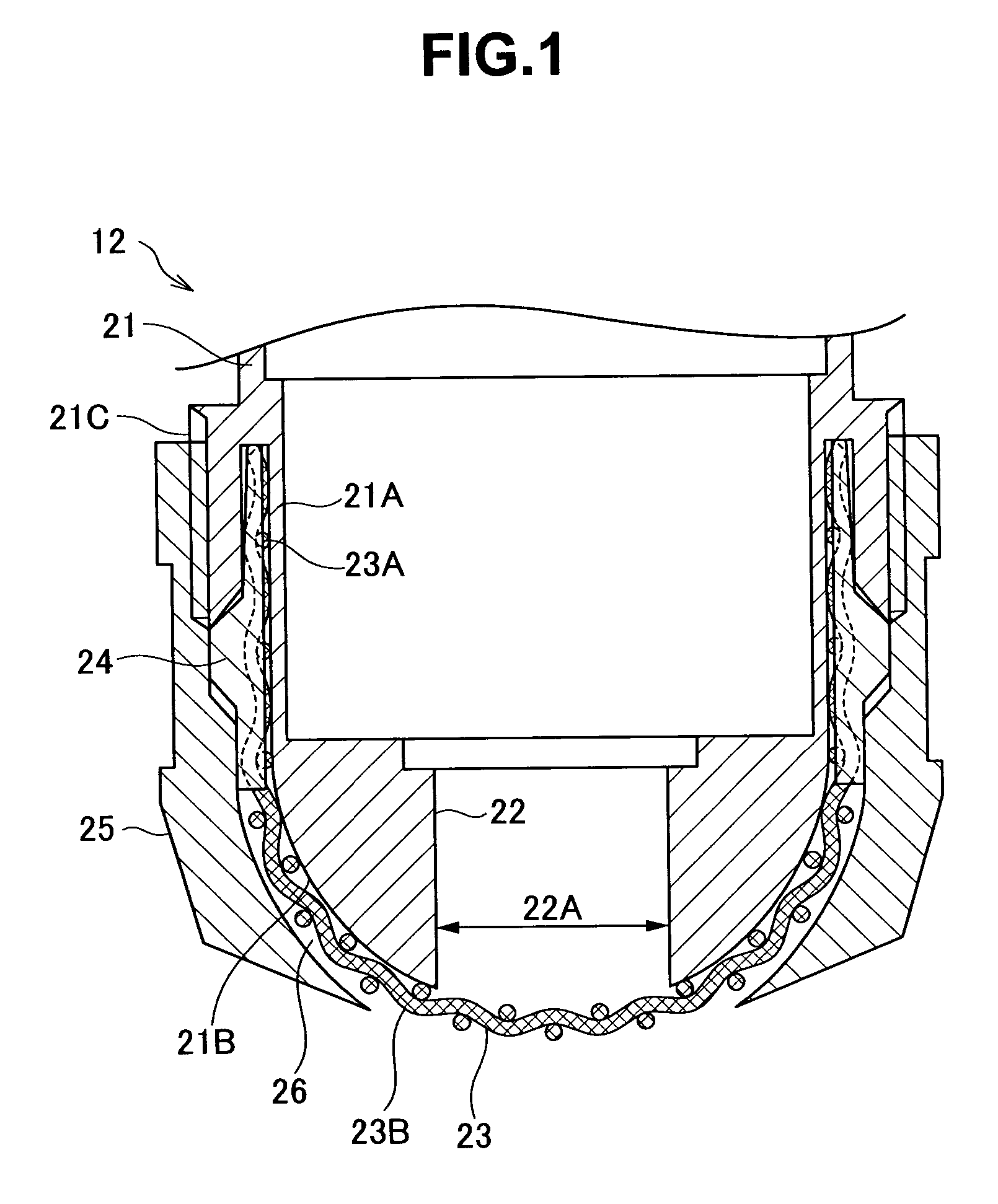
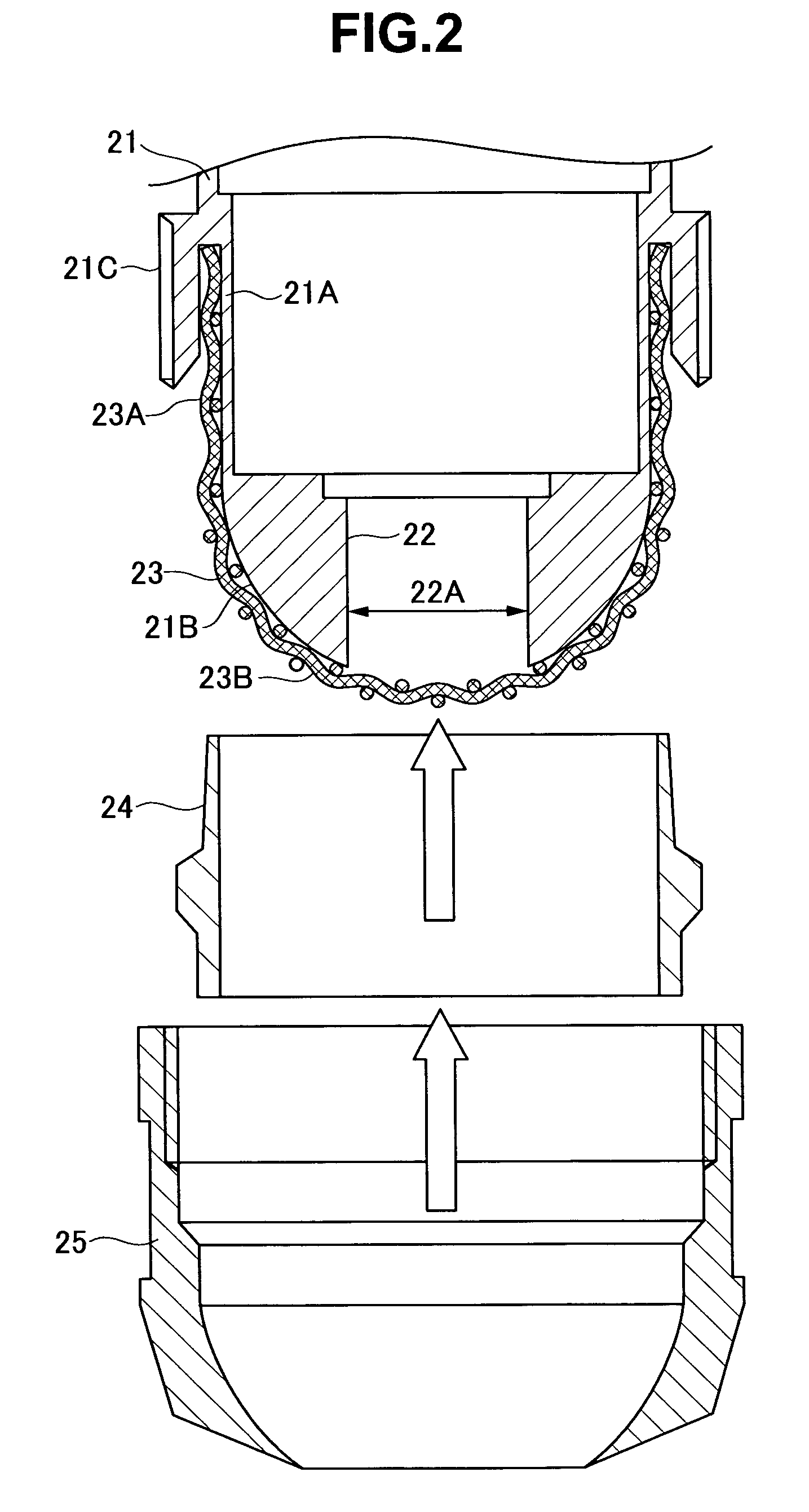
[0022] As shown in FIGS. 1 and 2, the filling nozzle 12 includes one net-like body 23 spreading on a front face of a discharge port 22 of a nozzle main body 21 and around the front face. The net-like body 23 is formed of a tube portion 23A and a hemispherical face portion 23B contiguous to a tip end side of the tube portion 23A. By mounting a tubular net retainer 24 to an outer periphery of the tube portion 23A fitted over a tubular outer peripheral portion 21A of the nozzle main body 21, the net-like body 23 is fixed to the nozzle main body 21. A cover-like net support 25 forming a discharge port peripheral wall portion is mounted to outer peripheries of the hemispherical f...

embodiment 2 figs

>

[0043] In the filling nozzle 12 in embodiment 2, as shown in FIGS. 6 and 7, in providing a net-like body 33 on a front face (a front face and an outer periphery as necessary) along the discharge direction of a discharge port 32 of a nozzle main body 31, an outer edge of the net-like body 33 is connected to an inner edge of a central hole portion 34A of a cover-like net support 34 screwed over (or fixed by a clamp to) an outer periphery of the nozzle main body 31 so that the outer edge and the inner edge are integrated with each other.

[0044] In the filling nozzle 12, the net-like body 33 is provided on an external side of the discharge port 32 of the nozzle main body 31 along the discharge direction (outside an opening 32A of the discharge port 32).

[0045] The filling nozzle 12 includes the net support 34 forming a discharge port peripheral wall portion on the outer periphery of the discharge port 32 of the nozzle main body 31 and a clearance 35 between the net support 34 and an ou...

embodiment 3 fig.8

Embodiment 3 FIG. 8

[0056] In the filling nozzle 12 of an embodiment 3, as shown in FIG. 8, the net-like body 23 is fixed to the nozzle main body 21 by using an O-ring 40.


PUM

PropertyMeasurementUnit
Capillary waveaaaaaaaaaa
Areaaaaaaaaaaa

Abstract

There is provided a liquid filling nozzle 12 with at least one net-like body 23 provided at a discharge port 22 of a nozzle main body 21, in which the net-like body 23 is provided on an external side of the discharge port 22.

Description

TECHNICAL FIELD [0001] The present invention relates to a liquid filling nozzle. BACKGROUND ART [0002] As a liquid filling nozzle into a container such as a bag, there is a nozzle in which a net-like body is provided at a discharge port of a nozzle main body as disclosed in Japanese Patent Application Laid-open No. 9-118314(Patent Document 1). In this liquid filling nozzle, by passing liquid through the net-like body, the liquid is made flow straight to prevent occurrence of bubbling when the liquid is filled into the container. [0003] In the liquid filling nozzle in the Patent Document 1, the net-like body is fixed to the discharge port in a through hole shape of the nozzle main body from inside. Therefore, the net-like body is provided inside an inside diameter of the discharge port. Therefore, when filling from the liquid filling nozzle has been finished, the liquid to be filled and existing in a region of a bore (inside the bore) of the discharge port adheres to meshes of the ne...

Claims


Application Information

Patent Timeline
IPC IPC(8): B65B39/00B65B3/22
CPCB65B3/22B67C2003/2645B67C3/2608B65B39/00
Inventor KUNII, MITSURUFUKUDA, TSUTOMU
Owner KAO CORP
Why Eureka
Try Eureka