Insulating Electricity Distribution Systems

Inactive Publication Date: 2007-10-04
CANATO
View PDF6 Cites 5 Cited by
  • Summary
  • Abstract
  • Description
  • Claims
  • Application Information

AI Technical Summary

Benefits of technology

[0025] One particular advantage of the present invention is that such a slot can typically be quite narrow and can be dimensioned to be quite small so that unintended contact with any components by the physical barrier provided by the shroud barrier is quite difficult. In particular the slots may be sufficiently small to prevent access of a body part, such as a digit, through the slot to the obstructed components.
[0026] Another particularly important advantage is that a panel which has a slot which runs inward from its edge (as described above) can be slid into place while a fuse and/or fuse cover is in place. This means that the fuse does not need to be removed which in turn means that the electricity supply across the fuse contacts need not be interrupted for fitting of the shroud.
[0027] Furthermore, once this initial panel is in place, the danger of receiving an accidental shock is already greatly reduced, though the safety can be further improved as described below.
[0028] It will be appreciated by those skilled in the art that the panel will be

Problems solved by technology

It will be appreciated that such distribution systems or panels are extremely hazardous.
They often run very high voltages.
Accordingly, the risk of serious injury or death from contact with either the distribution panel itself, or its underlying support frame, or indeed any of its supply intake or output components can be extremely high.
Even though the voltage in an output from such a distribution panel may be substantially stepped down, it was still represents a

Method used


Image

  • Insulating Electricity Distribution Systems
  • Insulating Electricity Distribution Systems
  • Insulating Electricity Distribution Systems

Examples


Example

DETAILED DESCRIPTION OF THE DRAWINGS

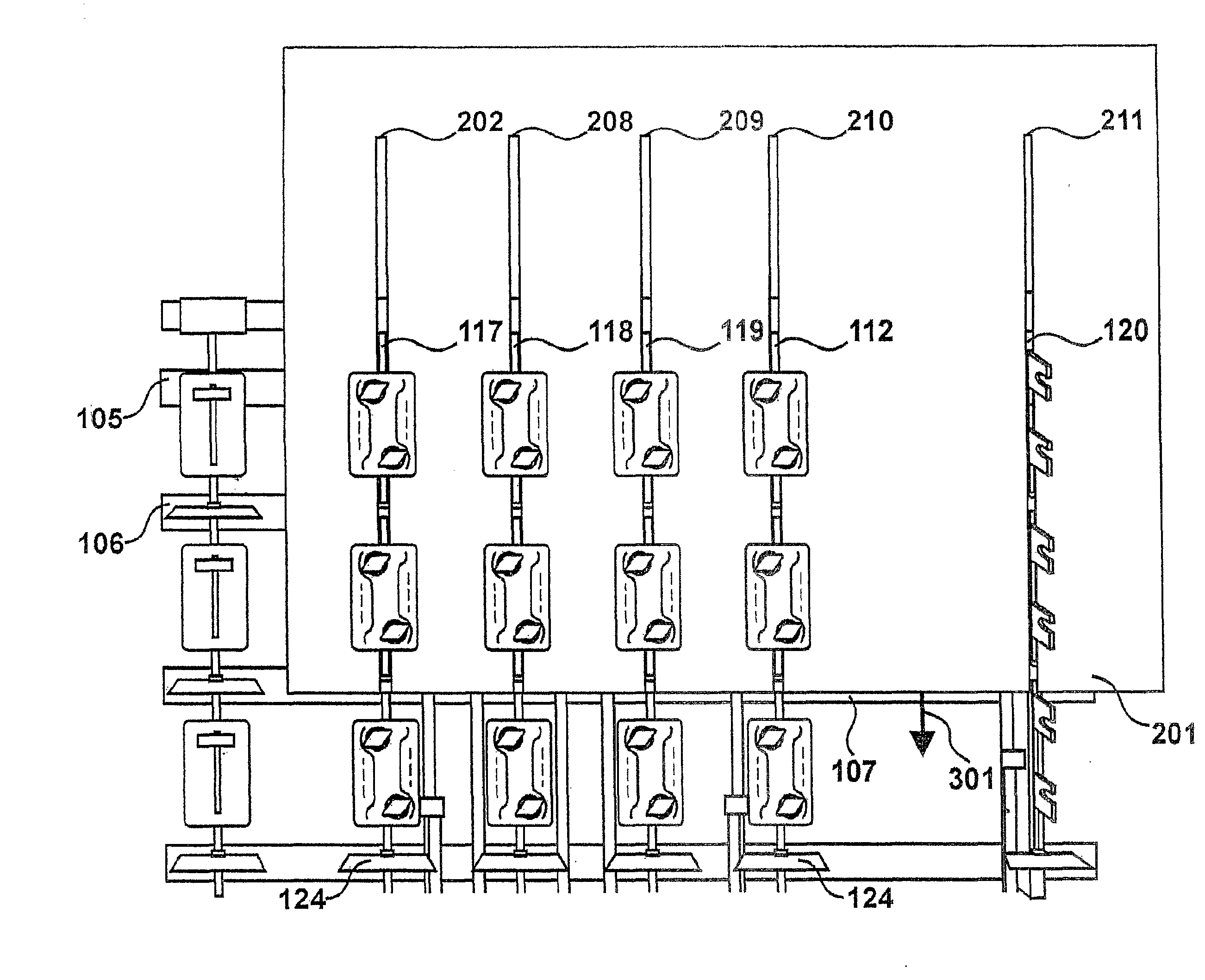
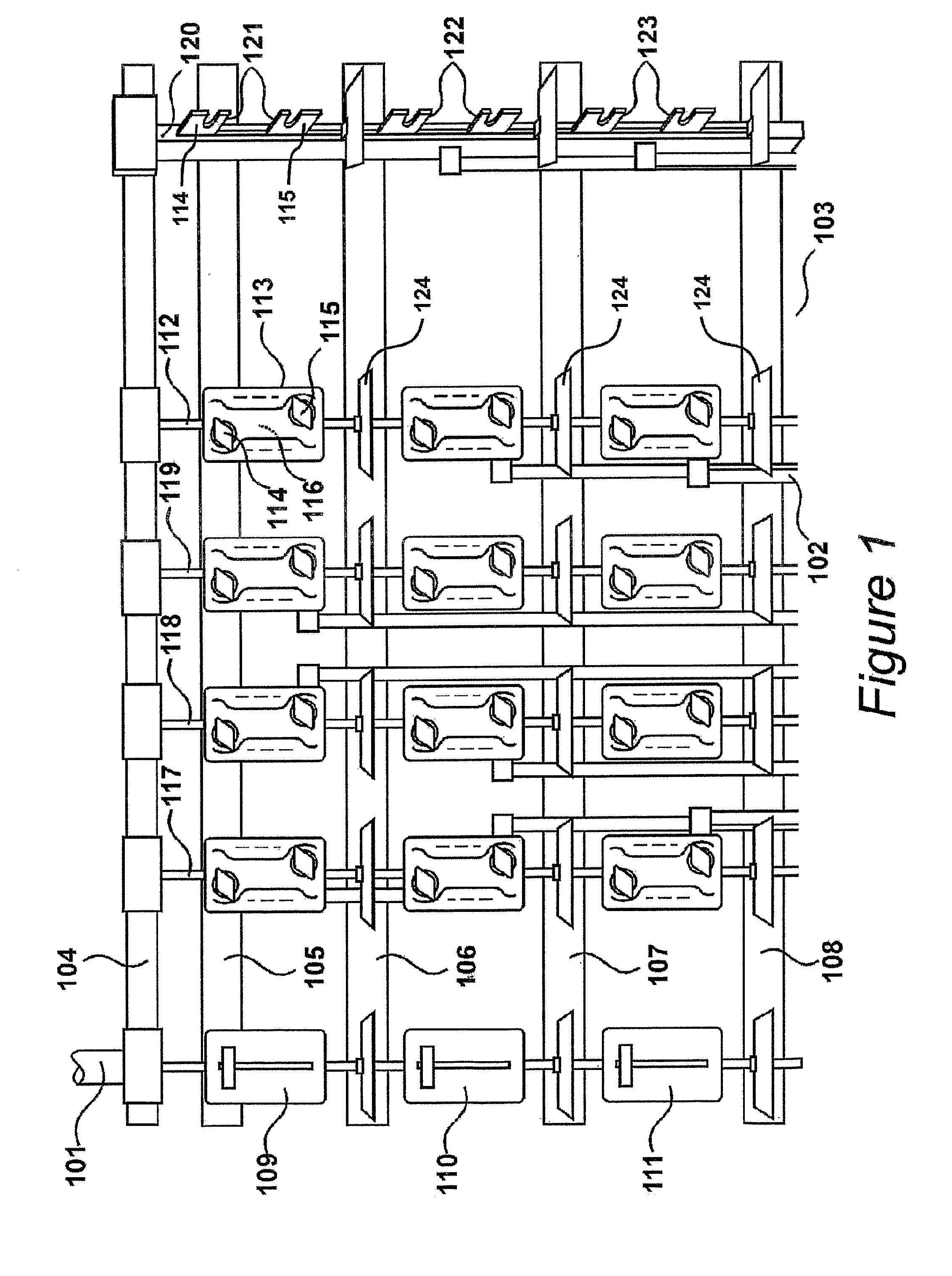
[0085] An electricity distribution system is shown in FIG. 1, as an electricity distribution station taking in power at a voltage of 10,000V supplied across high-tension lines 101 from a remote power supply station and outputting electricity across an electrical distribution panel to output lines 102 at a voltage of 220 V suitable for supply to an end user such as a domestic or commercial user.

[0086] One wall 103 of the building provides the substrate for support of a mounting frame 104. The mounting frame 104 is conductive at the same high-voltage of 10,000 V as the input lines 101 and is not insulated from the substrate, which is non-conductive. Generally mounted on the frame are a series of component parts of the distribution system, which will be referred here in as a “distribution panel”. The distribution panel will typically be held to the substrate 103 by the support frame 104. In general the distribution panel will comprise, at least one...


PUM


Abstract

A shroud barrier is provided for shrouding an electricity distribution system to and to mounted on a substrate. The system includes a support for supporting an electrical distribution panel on a substrate and an electrical distribution panel on the support. The distribution panel includes at least one busbar arranged on the support and at least one pair of spaced apart fuse contacts each having a free end, with the free ends thereof adapted to receive a fuse. One fuse contact is connected to the busbar and the other is connected to an outlet point. The fuse contacts are arranged so that the free ends thereof hold the fuse away from the busbar. The shroud barrier includes a sheet of insulating material slotted so as to slidingly fit across the fuse contacts, and dimensioned to cover the busbar and the support, so that substantially only the free ends of the fuse contacts extend through the slot.

Description

FIELD OF THE INVENTION [0001] The present invention relates to the field of insulating electricity distribution systems (apparatuses or arrangements) such as electricity distribution stations such as those which are commonplace. Of particular interest are electricity distribution systems which take in power at a voltage supplied across high-tension lines from a power supply station and output electricity at a voltage suitable for supply to an end user such as a domestic or commercial user. Such distribution systems are often referred to as electricity (sub) stations (or as a high voltage to low voltage electrical station). They are often housed either in a relatively small building or a floor-mounted container located in close proximity to a traffic network, such as a road or a street, and may even be of a size suitable for mounting on a pole. The latter are typically referred to as being mounted in a box. Of particular interest are all aspects of insulating, including component par...

Claims


Application Information

Patent Timeline
IPC IPC(8): H02B1/06H02B1/18
CPCH02B1/18H02B1/06H02B1/14
Inventor MCEVATT, FERGHAL
Owner CANATO
Why Eureka
Try Eureka