Apparatus for monitoring a measurement transmitter of a field device

Inactive Publication Date: 2008-03-18
ENDRESS HAUSER FLOWTEC AG
View PDF11 Cites 3 Cited by
  • Summary
  • Abstract
  • Description
  • Claims
  • Application Information

AI Technical Summary

Benefits of technology

[0006]An object of the invention is to provide an apparatus, with which the

Problems solved by technology

In the case of industrially-used measuring devices, climatically difficult conditions often prevail.
Under the previously-

Method used


Image

  • Apparatus for monitoring a measurement transmitter of a field device
  • Apparatus for monitoring a measurement transmitter of a field device

Examples


Example

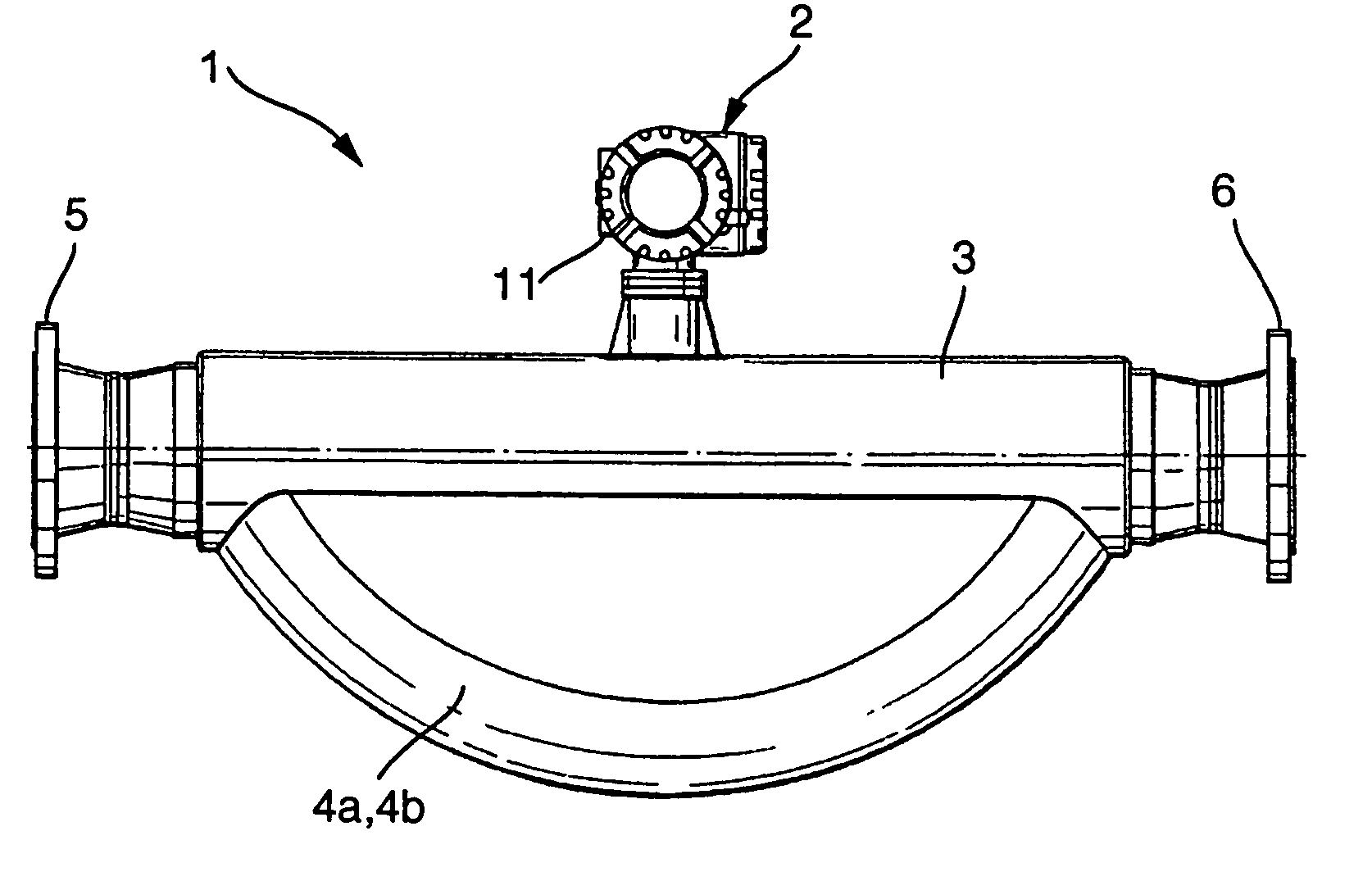
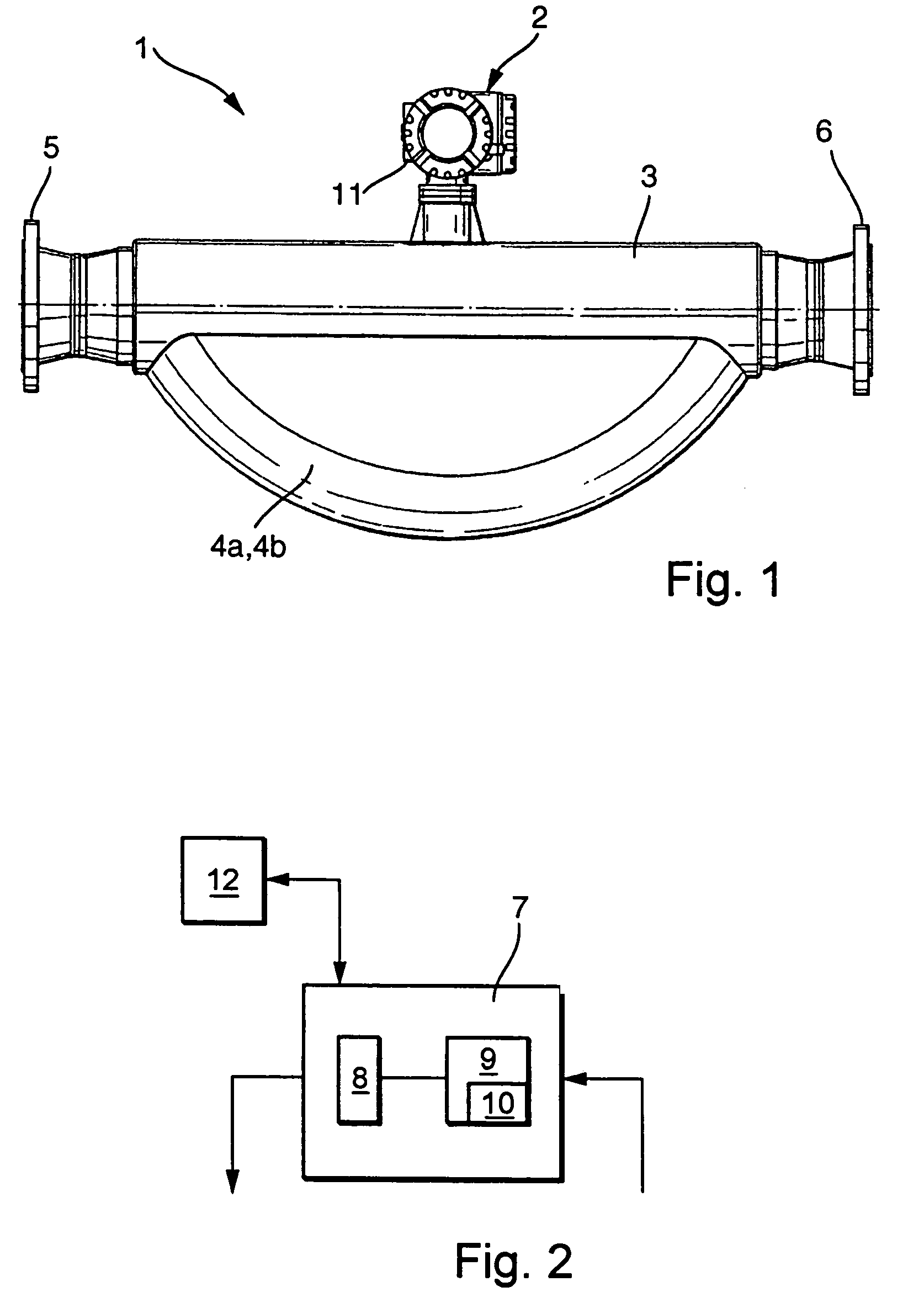
[0015]FIG. 1 shows a side view of a Coriolis measuring device 1, or a vibration-type measuring device, which is suited for measuring flow rate, density, and / or viscosity. The sensor 3, in operation, is inserted into a pipeline, not separately shown in FIG. 1, through which the medium flows. The medium can be steam or vapor, a gas, or a liquid. The measuring device 1, in the case represented here, is inserted into the pipeline using the flanges 5, 6. Of course, the connection into the pipeline can also be accomplished using other fasteners, e.g. Triclamp connectors, or threaded connections.

[0016]In the illustrated case, the sensor 3 has two parallel, curved measuring tubes 4a, 4b, through which the medium is conducted. The measuring tubes can also be straight.

[0017]It is equally possible to fit the Coriolis measuring device 1 with only one measuring tube 4.

[0018]In operation, the measuring tubes 4a, 4b are excited to tuning fork-like vibrations, preferably to resonance-vibrations, by...


PUM


Abstract

An apparatus for monitoring a measurement transmitter of a field device determining and/or monitoring a physical and/or chemical process parameter, wherein at least one sensor is provided inside the a housing, in which the transmitter is arranged. The sensor determines the temperature and relative humidity in the housing over a period of time in predetermined intervals, and a control-/evaluation-unit is provided, which, on the basis of the measured temperature and relative humidity, determines the absolute humidity and/or the dewpoint in the housing of the transmitter, and issues and alarm when the absolute humidity and/or the dewpoint in the housing of the transmitter reaches a critical value.

Description

FIELD OF THE INVENTION[0001]The invention relates to an apparatus for monitoring a measurement transmitter of a field device determining and / or monitoring a physical and / or chemical process parameter.BACKGROUND OF THE INVENTION[0002]The process parameter can be, for example, the mass or volume flow rate of a medium flowing through a measuring tube. Of course, the parameter can also be fill level, pressure, temperature, moisture content, pH or the concentration of a substance in a medium, or some other process parameter.[0003]In connection with the determining and / or monitoring of process parameters, the tendency is going increasingly in the direction of providing the user with, besides the actual measurement information, also information concerning the functioning or the operating life of the measuring device under the existing system- and / or process-conditions. Current catchwords in this connection are ‘Predictive Maintenance’ and ‘Mean Time Before Failure’. The goal of these effor...

Claims


Application Information

Patent Timeline
IPC IPC(8): G08B1/08G01D1/18G01D3/08G01F1/84G01F15/02
CPCG01D1/18G01D3/08G01F1/8431G01F1/8477G01F15/024
Inventor MATT, CHRISTIAN
Owner ENDRESS HAUSER FLOWTEC AG
Why Eureka
Try Eureka