Auto tip calibration in an extrusion apparatus

a three-dimensional modeling machine and extrusion tip technology, applied in the direction of additive manufacturing processes, manufacturing data acquisition/processing, instruments, etc., can solve the problems of model and possibly extrusion tip or head itself damage, build material may be misplaced or deformed, and need servicing

Active Publication Date: 2007-10-04
STRATSYS INC
View PDF34 Cites 280 Cited by
  • Summary
  • Abstract
  • Description
  • Claims
  • Application Information

AI Technical Summary

Problems solved by technology

If the extrusion tip is too far away from the base, then the build material may be misplaced or deformed.
Conversely, if the extrusion tip is too close to the base, then it may contact the model and cause damage to the model and possibly the extrusion tip or head itself.
However, the machines also require servicing from time to time such as when an extrusion tip may become unusable or unreliable due to a back-up or solidification of modeling material inside the tip.
When the flow of modeling material through the extrusion tip is obstructed installation of a new tip is typically necessary.
With

Method used


Image

  • Auto tip calibration in an extrusion apparatus
  • Auto tip calibration in an extrusion apparatus
  • Auto tip calibration in an extrusion apparatus

Examples


Embodiment Construction

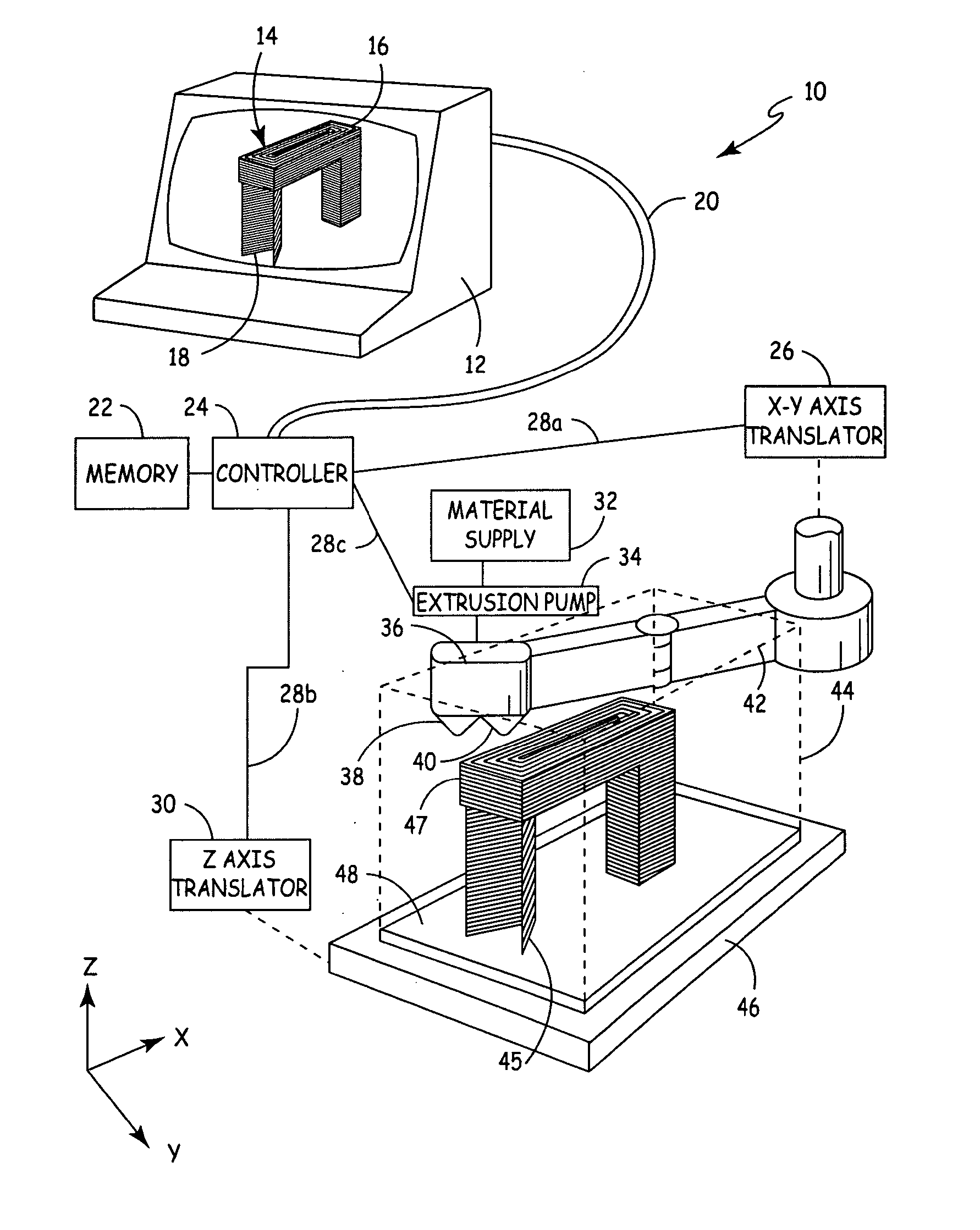
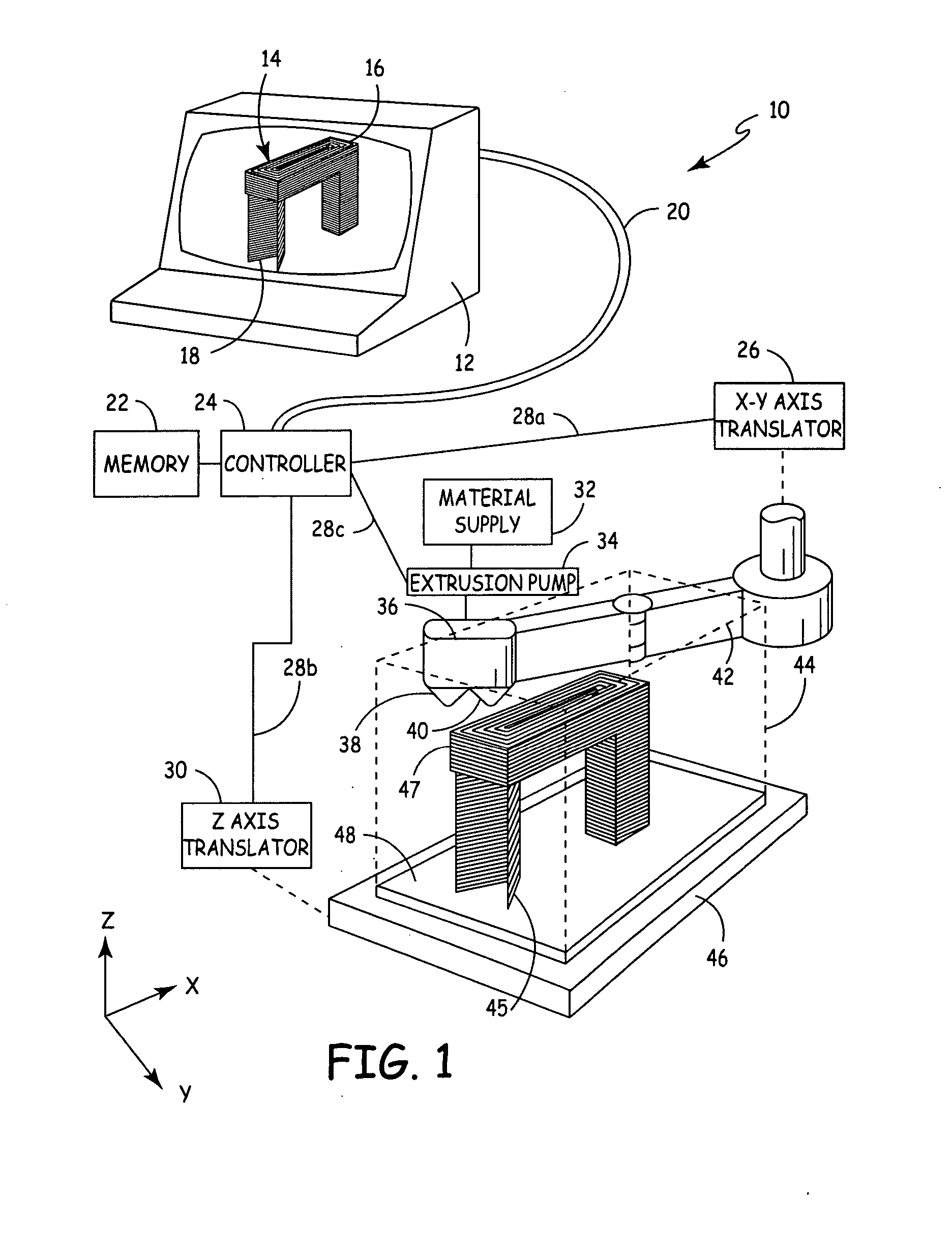
[0025]FIG. 1 shows a generic representation of a three-dimensional modeling system 10, of a type known in the art with which the present invention may be used. More specifically, the three-dimensional modeling system 10 illustrated in FIG. 1 is an extrusion-based layered modeling system. A computer aided design (CAD) program resident in processor 12 generates a file describing the geometry of part 14 to be created. A slicing program (shown as resident in processor 12, but which may alternatively be resident in a separate processor) algorithmically subdivides the file into modeling material volume elements 16 corresponding to shapes that can be extruded from a model material extrusion tip 38. Additional support material volume elements 18 are added as necessary to provide a mechanical support 45 to a model 47 of the part 14 during its construction.

[0026] Modeling system 10 utilizes a pair of dispensers 38 and 40, to dispense the different materials used to construct model 47 and sup...


PUM

PropertyMeasurementUnit
Lengthaaaaaaaaaa
Structureaaaaaaaaaa
Heightaaaaaaaaaa

Abstract

The present invention is a method for performing a calibration routine of a deposition device in a three-dimensional modeling machine that deposits a material to build up three-dimensional objects as directed by a controller on a substrate mounted on a platform. The method comprises generating a material build profile, which represents a three-dimensional structure at defined locations. A relative position of the material build profile is then determined. An expected build profile is identified and then compared to the determined relative position of the material build profile to identify any difference which represents an offset. The modeling system then positions the deposition device based upon the offset.

Description

CROSS-REFERENCE TO RELATED APPLICATION(S) [0001] None. BACKGROUND OF THE INVENTION [0002] The present invention relates to the fabrication of three-dimensional objects using additive process modeling techniques. More particularly, the invention relates to a method for calibrating extrusion tips in a three-dimensional modeling machine. [0003] Additive process modeling machines make three-dimensional models by building up a modeling medium, usually in planar layers, based upon design data provided from a computer aided design (CAD) system. A mathematical description of a physical part to be created is usually split into planar layers, and those layers are individually shaped and applied to produce the final part. Three-dimensional models are used for functions including aesthetic judgments, proofing the mathematical CAD model, forming hard tooling, studying interference and space allocation, and testing functionality. The dominant application of layered manufacturing in recent years h...

Claims


Application Information

Patent Timeline
IPC IPC(8): D04H1/16
CPCB29C67/0088B29C67/0055B29C64/106B33Y30/00B29C64/393B33Y50/02
Inventor DUNN, BENJAMIN N.COMB, JAMES W.ERICKSON, HANS P.WANZEK, JASON P.
Owner STRATSYS INC
Why Eureka
Try Eureka