Image display apparatus and method

Inactive Publication Date: 2007-10-04
KK TOSHIBA
View PDF27 Cites 28 Cited by
  • Summary
  • Abstract
  • Description
  • Claims
  • Application Information

AI Technical Summary

Benefits of technology

[0007]The present invention is directed to an apparatus and a method for

Problems solved by technology

In this case, the image display apparatu

Method used


Image

  • Image display apparatus and method
  • Image display apparatus and method
  • Image display apparatus and method

Examples


Example

First Embodiment

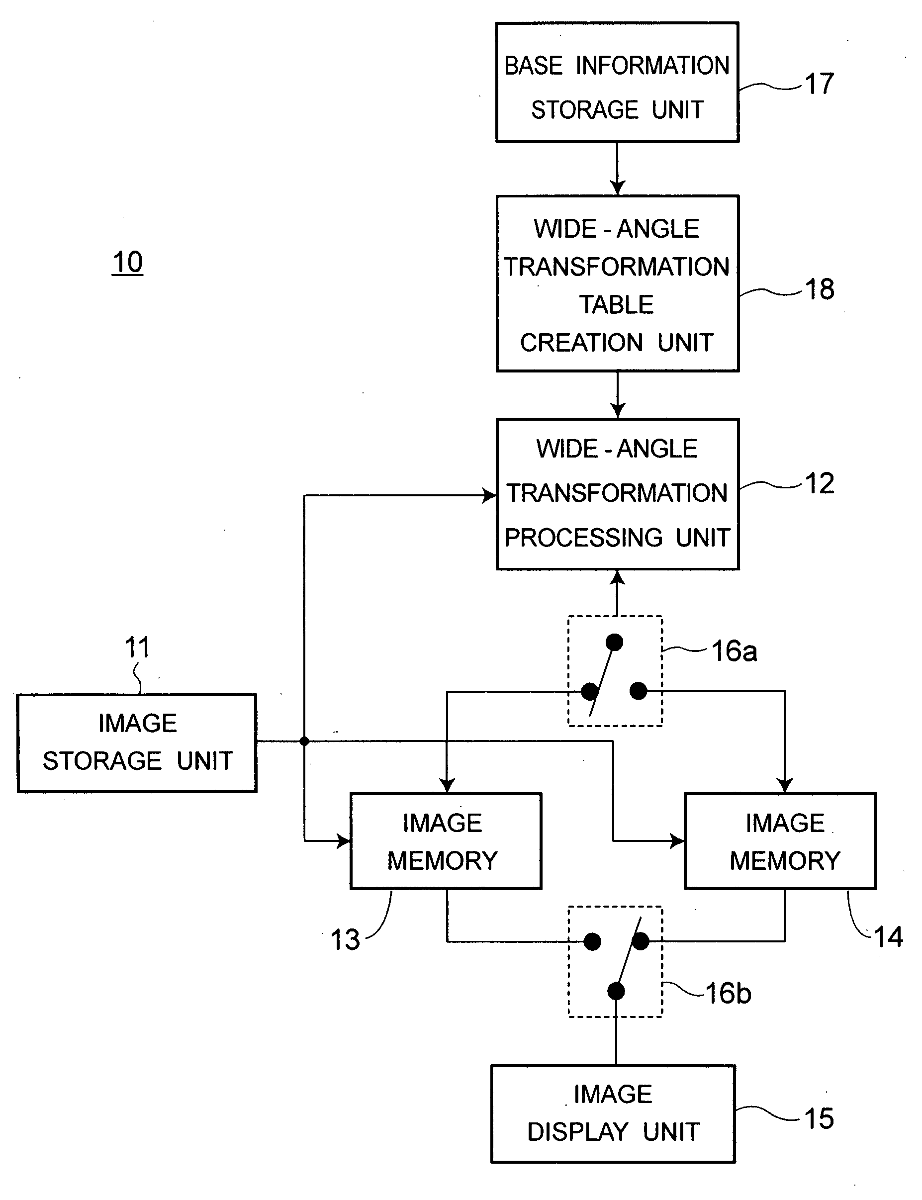
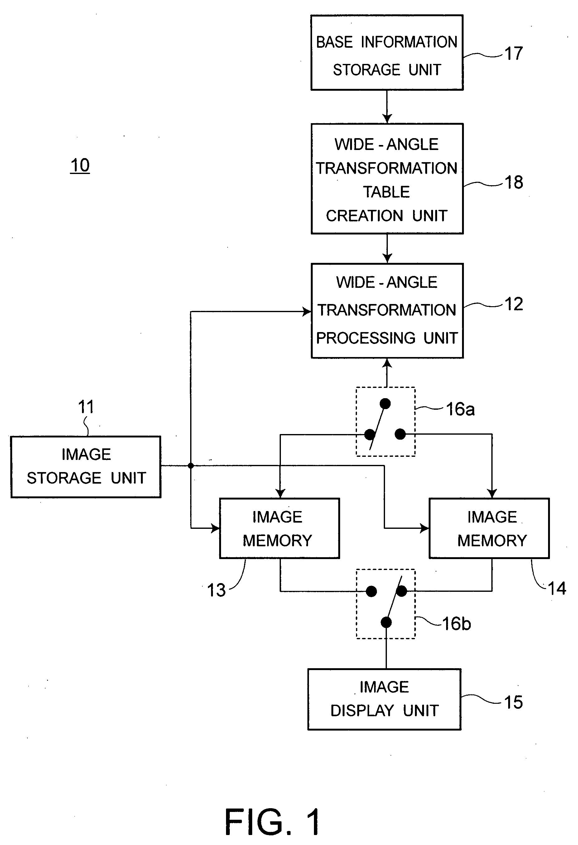
[0027]FIG. 1 is a block diagram of an image display apparatus 10 according to the first embodiment of the present invention. The image display apparatus 10 includes an image storage unit 11, a wide angle transformation processing unit 12, image memories 13 and 14, an image display unit 15, change-over switches 16a and 16b, a base information storage unit 17, and a wide angle transformation table creation unit 18.

[0028]The image storage unit 11 is, for example, a memory apparatus such as a hard disk drive or a semiconductor memory, which stores and outputs image information (including both still picture and motion picture). The wide-angle transformation processing unit 12 preserves a wide-angle transformation table, and performs wide-angle transformation of an image (output from the image storage unit 11) using the wide-angle transformation table. By rewriting contents of the image memories 13 and 14 by the wide-angle transformation processing unit 12, the wide-angle...

Example

Second Embodiment

[0078]FIG. 7 is a block diagram of an image display apparatus 20 according to the second embodiment. The image display apparatus 20 includes the image storage unit 11, an aliasing prevention processing unit 21, a field subsample processing unit 22, the wide-angle transformation processing unit 12, the image memories 13 and 14, an image display unit 23, change-over switches 16a and 16b, the base information storage unit 17, and the wide-angle transformation table creation unit 18.

[0079]FIG. 8 is a block diagram of the image display unit 23 in FIG. 7. The image display unit 23 is a display apparatus of projection type, and includes a source of light 31, a collimetor lens 32, a display element 33, a wobbling element 34, a projection lens 35, a screen 36, a signal processing unit 37, a display element driving unit 38, and a wobbling element driving unit 39.

[0080]As to the source of light 31, for example, a source of light of high brightness such as a metal halide lamp ...


PUM


Abstract

An image display unit has a display region with a higher resolution than a number of pixels of an image. A base information storage unit stores viewing position information of a viewer and size information of the display region. A wide-angle transformation unit calculates a central area including a viewing center of the viewer of the display region using the viewing position information and the size information, divides the image into a first pixel area corresponding to the central area and a second pixel area corresponding to a peripheral area other than the central area, and transforms the first pixel area and the second pixel area by magnifying. A magnification ratio of the first pixel area is less than a magnification ratio of the second pixel area. The image display unit displays an image including the transformed first pixel area and the transformed second pixel area.

Description

CROSS-REFERENCE TO RELATED APPLICATIONS[0001]This application is based upon and claims the benefit of priority from prior Japanese Patent Application No. 2006-091694, filed on Mar. 29, 2006; the entire contents of which are incorporated herein by reference.FIELD OF THE INVENTION[0002]The present invention relates to an apparatus and a method for displaying an image with a wide field of view.BACKGROUND OF THE INVENTION[0003]In order for a viewer to feel hyper-reality, a field of view above at least 30° is necessary, and an image display apparatus having a large field of view is necessary. Such kind image displays are disclosed in the following references.[0004](A) Japanese Patent Publication No. 2002-148711[0005](B) Toshiki Nagumo, “A Study of an Electric Power Plant Training Environment Using a Small Cylindrical Screen”, The Virtual Reality Society of Japan, Vol. 4, No. 3, pp 521-529 (1999)[0006]In these references, an image is projected onto a screen having a spherical surface. By ...

Claims


Application Information

Patent Timeline
IPC IPC(8): G09G5/02
CPCG09G5/00H04N9/3197H04N9/3188G09G2340/0407
Inventor OKUMURA, HARUHIKOSASAKI, TAKASHIHOTTA, AIRA
Owner KK TOSHIBA
Why Eureka
Try Eureka