Remote control system including remote controller with image pickup function

Inactive Publication Date: 2007-10-04
FUNAI ELECTRIC CO LTD
View PDF6 Cites 69 Cited by
  • Summary
  • Abstract
  • Description
  • Claims
  • Application Information

AI Technical Summary

Benefits of technology

[0012]According to the present invention, a remote control system includes a remote controller for remotely operating an equipment, and a cradle connected to a commercial power supply and having a charging function for the remote controller, wherein the remote controller includes an image pick-up unit and a communication unit capable of connecting the remote controller to a network; and the cradle includes a light unit for increasing illuminance of a field of view of the image pick-up unit.
[0014]According to the present invention, the remote controller including the image pick-up unit can transmit the image picked up by the image pick-up unit to a server or the like through the network, and further, when illuminance of the field of view of the image pick-up unit is short, lighting the light unit included in the cradle enables the remote controller to function as a monitoring camera.
[0016]Thus, according to the present invention, equipment that the user does not need to carry can assume the function as the monitoring camera.
[0017]Moreover, according to the present invention, the light unit having a relatively large power consumption is provided in the fixable cradle instead of the remote controller to be carried in the room or the like, so that a battery life of the remote controller itself can be made longer.
[0018]Moreover, according to the present invention, since the image pick-up unit of the remote controller executes the image pickup operation provided that the remote controller is connected to the cradle, it is possible to avoid a situation where the image pickup operation is not executed due to the user forgetting the operation and the like, thereby enabling the remote controller to surely function as the monitoring camera.

Problems solved by technology

In a case where the digital camera is adapted to assume the function as the monitoring camera as shown in Japanese Patent Laying-Open No. 2003-338950, Japanese Patent Laying-Open No. 2004-080309, and Japanese Patent Laying-Open No. 2004-140589, there arises a problem that a user cannot carry the digital camera when the digital camera is made to monitor a room in his or her absent home or when the digital camera is made to monitor a user's car left behind while he or she goes sightseeing on visit to a sightseeing spot.

Method used


Image

  • Remote control system including remote controller with image pickup function
  • Remote control system including remote controller with image pickup function
  • Remote control system including remote controller with image pickup function

Examples


Embodiment Construction

[0035]Hereinafter, referring to the drawings, an embodiment of the present invention is described. In the following description, identical reference numerals designate identical parts. Names and functions thereof are also identical. Accordingly, their detailed descriptions are not repeated.

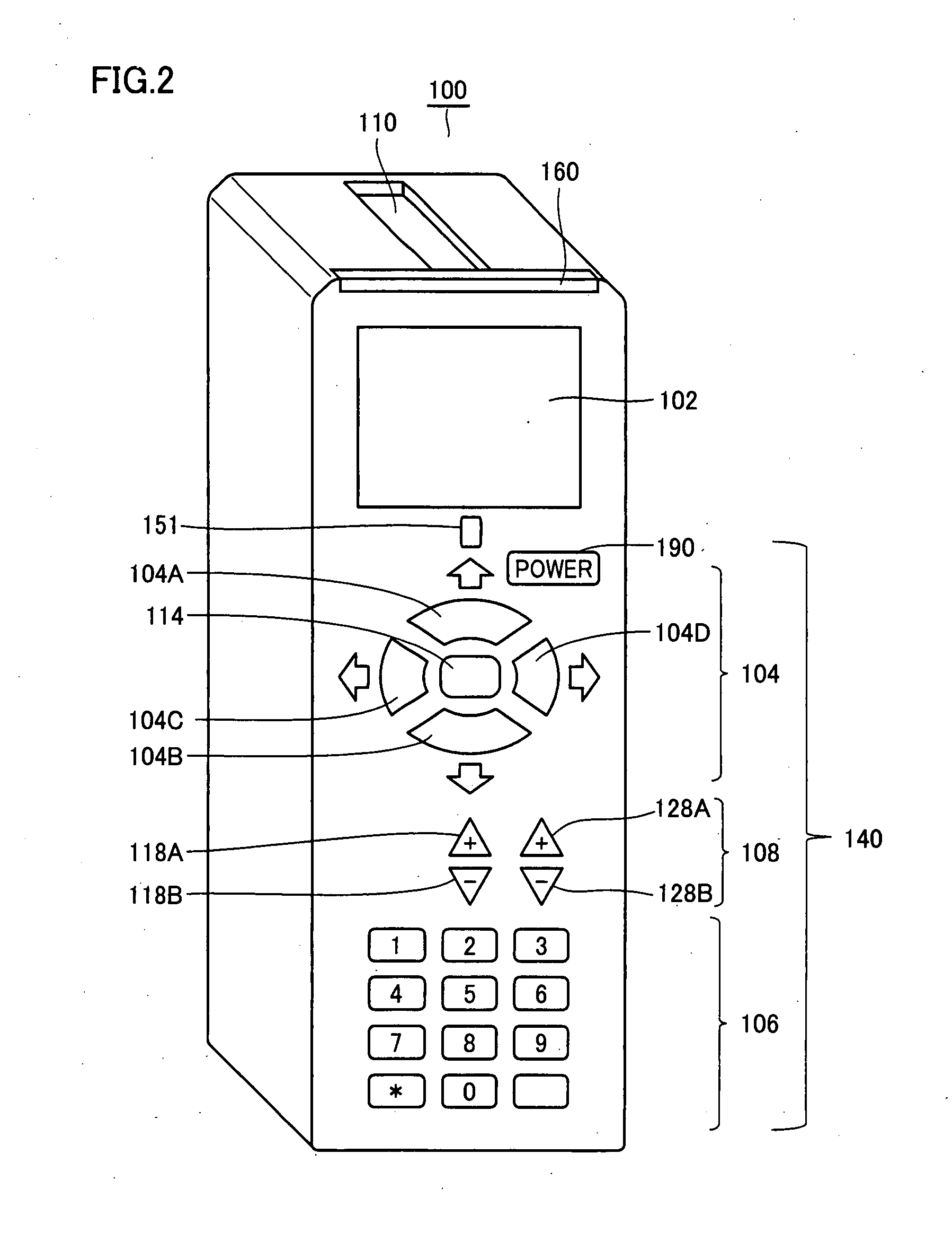
[0036]First, a use aspect of a remote controller 100 composing a remote control system according to the present invention is described.

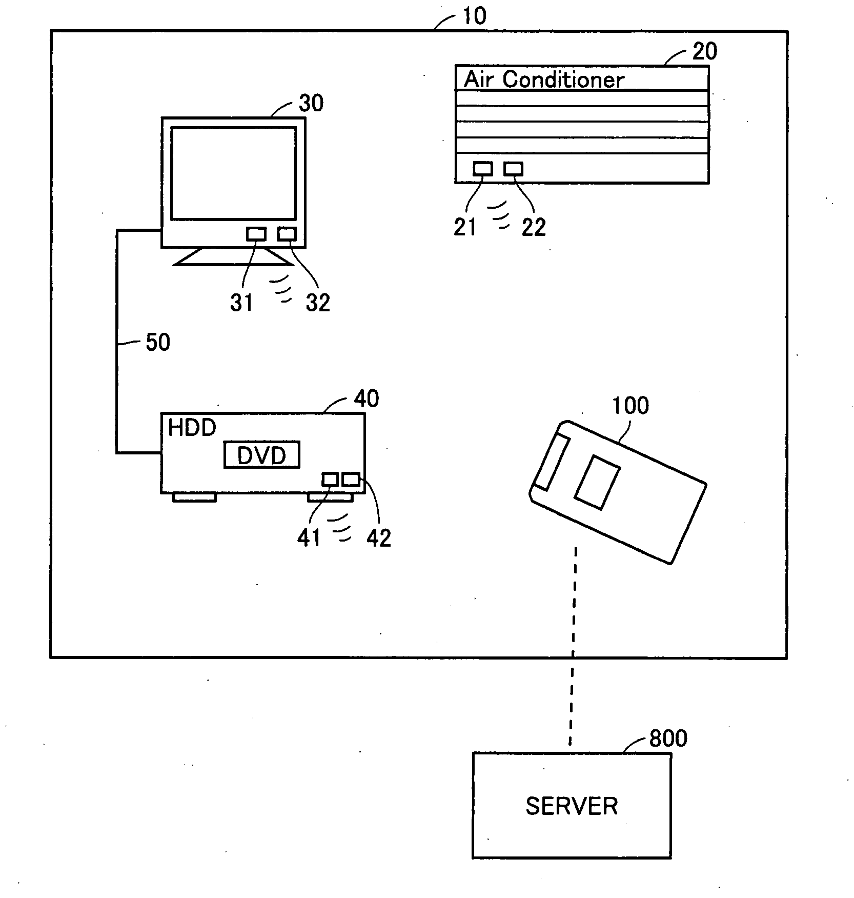
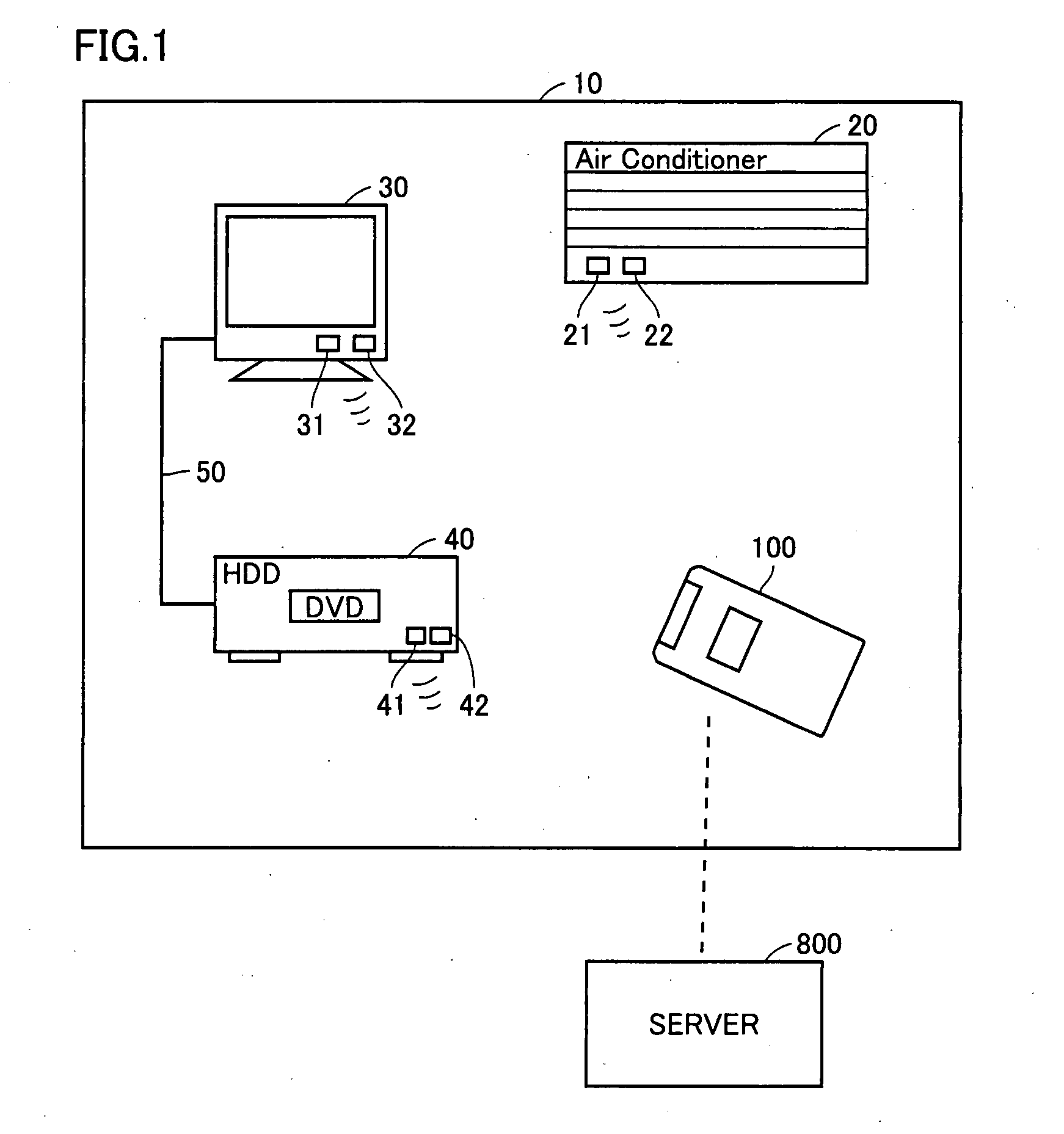
[0037]Referring to FIG. 1, in a room 10, an air conditioner 20, a television 30, and an HDD recorder 40 are arranged. Air conditioner 20 includes a light emitter 21 for emitting a light signal including identification information on the air conditioner itself, and a light receiver 22 for receiving a light control signal emitted by remote controller 100. Television 30 includes a light emitter 31 for emitting a light signal including identification information on the television itself, and a light receiver 32 for receiving a light control signal emitted by remote con...


PUM


Abstract

A remote control system is made up by a remote controller for remotely operating equipment such as an air conditioner and a television, and a cradle connected to a commercial power supply and having a charging function for the remote controller. The remote controller is equipped with a camera and a communication unit capable of communicating through a network. The cradle is equipped with a light unit such as an LED.

Description

BACKGROUND OF THE INVENTION[0001]1. Field of the Invention[0002]The present invention relates to a remote control system, and particularly to a remote control system including a remote controller with a camera and a cradle of the remote controller.[0003]2. Description of the Background Art[0004]Conventionally, various techniques utilizing a digital camera as a monitoring camera have been disclosed.[0005]For example, in Japanese Patent Laying-Open No. 2003-338950, there is disclosed a technique in which a cradle detachably supporting a digital camera is equipped with a function of moving the digital camera in a plurality of directions.[0006]Moreover, in Japanese Patent Laying-Open No. 2004-080309, there is disclosed a technique in which a cradle is configured so as to be powered from an automobile, so that a digital camera connected to the cradle can perform image pick-up operation for a long time even in a car.[0007]Furthermore, in Japanese Patent Laying-Open No. 2004-140589, there ...

Claims


Application Information

Patent Timeline
IPC IPC(8): H04N5/232G06F13/00G08B25/00H04N5/00H04N7/18H04Q9/00
CPCH04N1/00127H04N5/225H04N5/2257H04N5/4403H04N2005/4428H04N21/43615H04N2201/0084H04N21/4131H04N21/42222H04N21/4227H04N2101/00H04N21/42204H04N23/57H04N23/00
Inventor TAKESHITA, MASAHIROMASAKI, YASUOISHIMOTO, KOUICHI
Owner FUNAI ELECTRIC CO LTD
Why Eureka
Try Eureka