Assembly of heat-dissipating device and circuit board

Inactive Publication Date: 2007-10-04
AOPEN
View PDF29 Cites 13 Cited by
  • Summary
  • Abstract
  • Description
  • Claims
  • Application Information

AI Technical Summary

Benefits of technology

[0009]Therefore, the object of the present invention is to provide an assembly of a heat-dissipating device and a circuit board that has shock-absorbing functionality and that can ensure stable securing.
[0023]In view of the provision of the resilient washers in the assembly of the heat-dissipating device and the circuit board of this invention, the heat-dissipating device can be secured stably on the circuit board. In addition, when the heat-dissipating device is subjected to an external force during impact, because the resilient washers abut against the circuit board, a portion of the external force could be absorbed or distributed to the circuit board. As a result, not only can the upper surface of the circuit board be prevented from damage, the likelihood of damage to the heat-generating component due to the external force can be reduced as well.

Problems solved by technology

However, when using the specially designed fastening member for assembly, mold costs for manufacturing the fastening member are incurred, thereby resulting in higher production costs.
However, since friction is generated upon contact between a bottom face of the shank part 132 of each screw 131 and the top surface of the circuit board 2, the surface of the circuit board 2 is damaged, which can result in the likelihood of a short circuit.
This, however, results in a problem that the heat-dissipating device 1 is prone to be undesirably removed.
However, because of a clearance between the shank part 138 of each screw 131 and the wall of the corresponding hole 21, and a clearance between the top surface of the circuit board 2 and a fastening ring 137 that engages an outer surface of the shank part 138, the heat-dissipating device 1 can hardly be secured stably on the circuit board 2, which likewise results in the heat-dissipating device 1 being prone to be undesirably removed.
Moreover, since the screws 131 do not abut directly against the circuit board 2, when the heat-dissipating device 1 is subjected to an external force (A) during impact, the heat-dissipating device 1 is likely to press directly and downwardly the central processing unit 20, thereby resulting in damage to the central processing unit 20 due to the applied force.

Method used


Image

  • Assembly of heat-dissipating device and circuit board
  • Assembly of heat-dissipating device and circuit board
  • Assembly of heat-dissipating device and circuit board

Examples


Embodiment Construction

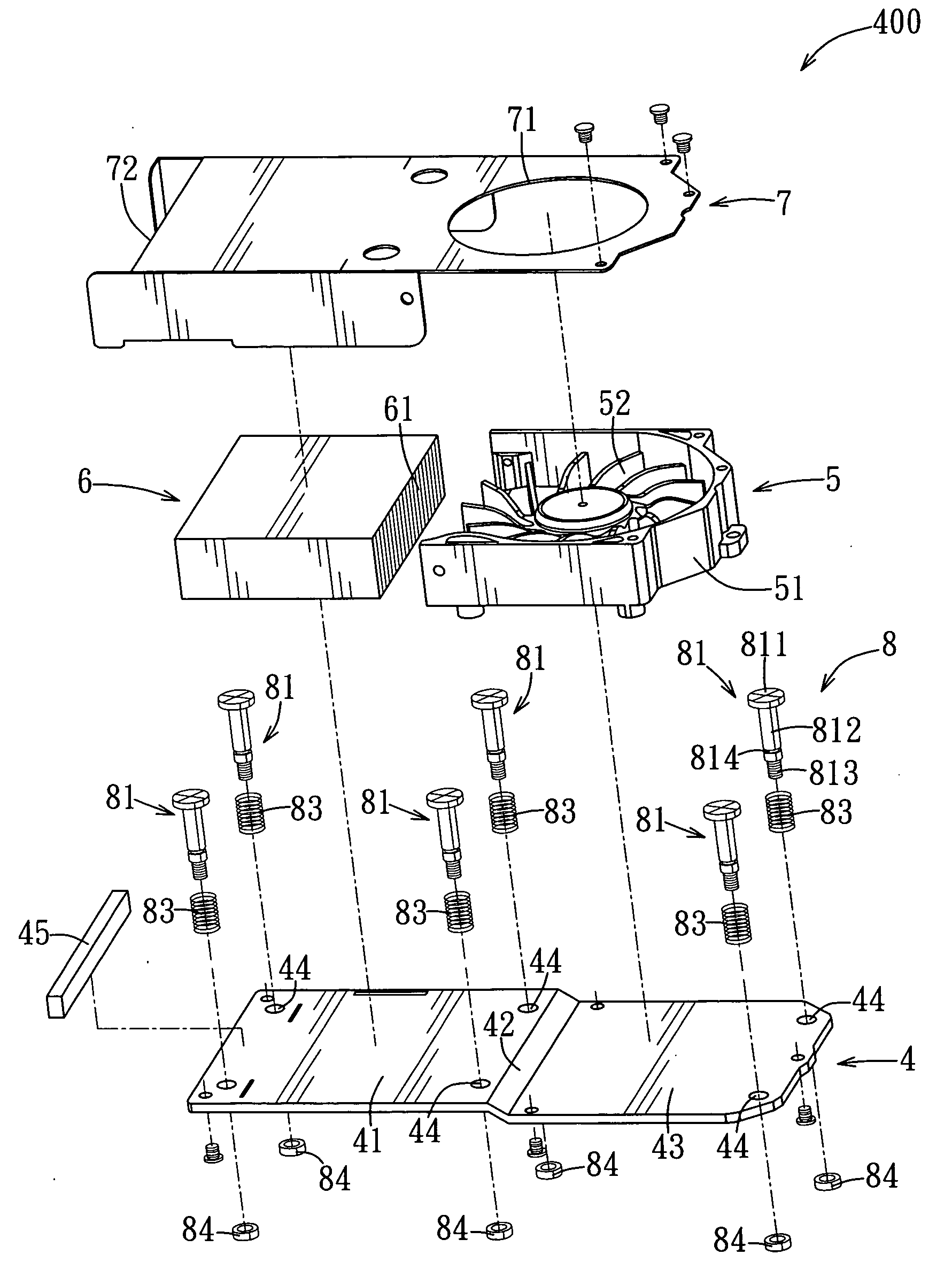
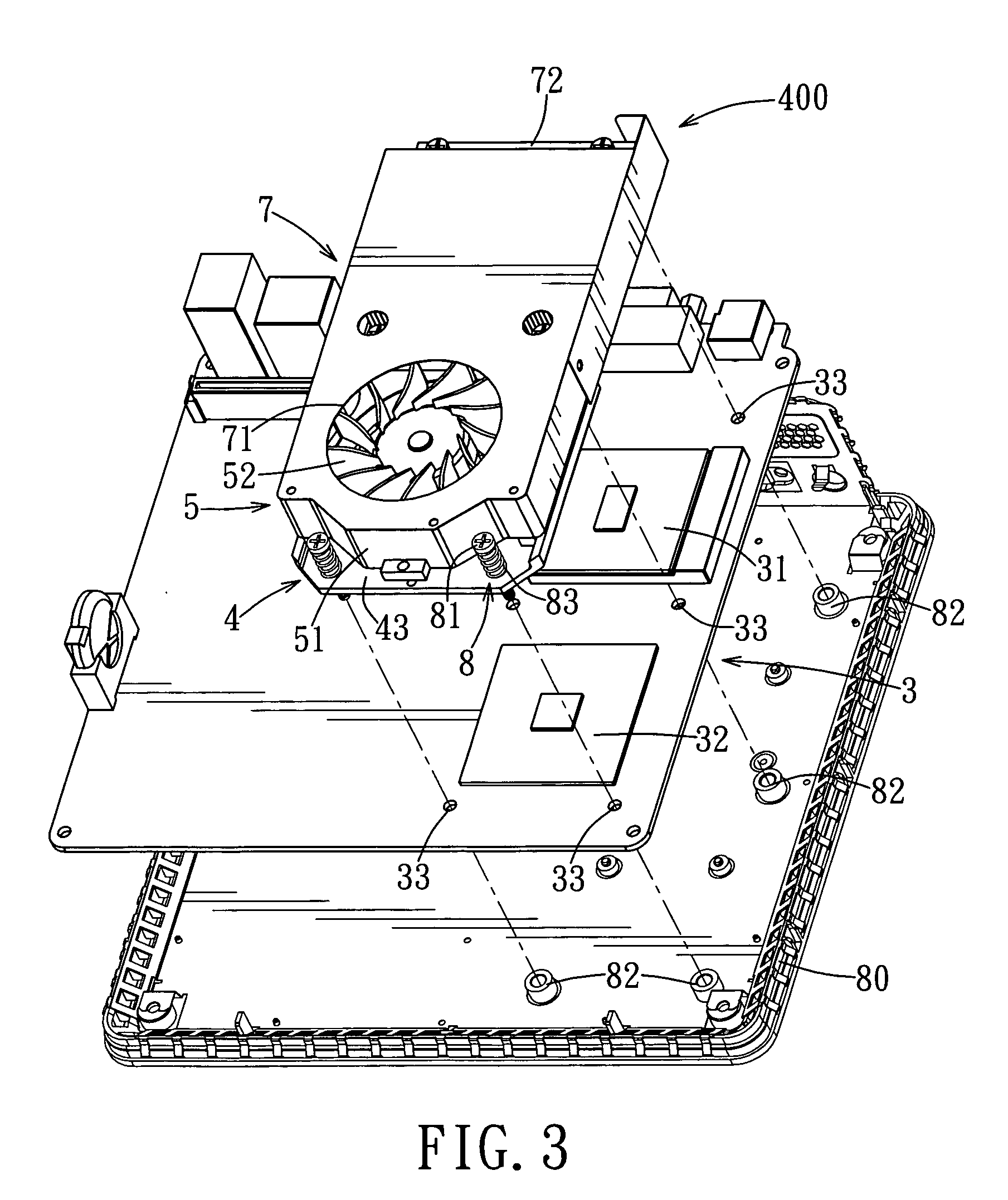
[0032]Referring to FIGS. 3 and 4, the preferred embodiment of an assembly according to the present invention is shown to comprise a circuit board 3 and a heat-dissipating device 400.

[0033]The circuit board 3 has two heat-generating components 31, 32 mounted on an upper surface thereof, and is formed with three pairs of spaced apart board holes 33. In this embodiment, the heat-generating component 31 disposed proximate to the rear side of the circuit board 3 is a central processing unit (CPU), whereas the heat-generating component 32 disposed proximate to the front side of the circuit board 3 is a north bridge chipset. The circuit board 3 is mounted on a housing 80.

[0034]The heat-dissipating device 400 includes a base plate 4 made of copper and elongated in shape, a heat-dissipating fan 5 mounted on a front side of the base plate 4, a heat-dissipating component 6 mounted on a rear side of the base plate 4, a cover body 7 for covering the heat-dissipating fan 5 and the heat-dissipatin...


PUM


Abstract

In an assembly of a heat-dissipating device and a circuit board, the circuit board has a heat-generating component and is formed with board holes. The heat-dissipating device includes a base plate, a heat-dissipating component, fastening members, biasing members, engaging members, and resilient washers. The base plate abuts against the heat-generating component, and is formed with through-holes. The heat-dissipating component is disposed on the base plate. Each fastening member has a shank part extending through one through-hole and one board hole, a head part, and a threaded connection part. Each biasing member abuts against the base plate and the head part of one fastening member. Each engaging member is disposed at a lower surface of the circuit board and engages the threaded connection part of one fastening member. Each washer is sleeved on one fastening member, and abuts against an upper surface of the circuit board.

Description

CROSS-REFERENCES TO RELATED APPLICATIONS[0001]This application claims the priority of Taiwanese Application No. 095205579, filed Apr. 3, 2006, the full disclosure of which is incorporated herein by reference.BACKGROUND OF THE INVENTION[0002]1. Field of the Invention[0003]The invention relates to an assembly of a heat-dissipating device and a circuit board, more particularly to an assembly including a heat-dissipating device, a circuit board and resilient washers.[0004]2. Description of the Related Art[0005]In general, a heat-dissipating device and a circuit board are assembled using a specially designed fastening member to achieve the effect of secure engagement. However, when using the specially designed fastening member for assembly, mold costs for manufacturing the fastening member are incurred, thereby resulting in higher production costs.[0006]Another manner of assembly uses relatively low cost screw fasteners. As shown in FIG. 1, a heat-dissipating device 1 includes a base pla...

Claims


Application Information

Patent Timeline
IPC IPC(8): H05K7/20
CPCH01L23/4006H01L23/467H01L2924/0002H01L2924/00
Inventor LO, KUN-HANGHSIEH, MING-FENG
Owner AOPEN
Why Eureka
Try Eureka