Illumination Unit and Illumination Apparatus

a technology of illumination apparatus and illumination unit, which is applied in the direction of light heating apparatus, semiconductor devices of light sources, planar light sources, etc., can solve the problems of limited installation of illumination light sources, and achieve the effects of extending the irradiation distance of light, high illumination, and constant flat illuminance distribution

Inactive Publication Date: 2007-10-04
MEERE
View PDF8 Cites 24 Cited by
  • Summary
  • Abstract
  • Description
  • Claims
  • Application Information

AI Technical Summary

Benefits of technology

[0008] An advantage of the present invention is that it provides an illumination unit by which an illumination region having a constant flat illuminance distribution is obtained at high illuminance while electric power is saved and which can extend the irradiation distance of light without color shading or shadow being generated in the illumination region, and an illumination apparatus including the illumination unit.
[0009] (1) According to a first aspect of the invention, an illumination unit using a light-emitting diode as a light source includes a light emitting unit having a plurality of light emitting diodes arranged on a base; first reflecting sections that are provided to correspond to the respective plurality of light emitting diodes on the light emitting side of the light emitting unit, each first reflecting section having a parabolic surface whose focal position is the light emitting surface of the light emitting diode; and a pair of second reflecting sections that are arranged parallel to the arrangement direction of the light emitting diodes on the light emitting side of the first reflecting section across the light emitting diodes, each second reflecting section having a plate-shaped reflecting surface which reflects light from the light emitting diode toward the light emitting side.
[0010] According to the illumination unit, the first reflecting section reflects light from the light emitting diode toward the light emitting side, and the second reflecting section reflects light from the light emitting diode toward the light emitting side. Then, while electric power is saved, a uniform illuminance distribution can be obtained at high illuminance, and an irradiation distance can be extended.
[0011] When light from the light emitting diode is reflected by the first reflecting section whose reflecting section is a parabolic surface, parallel light can be produced with high precision, thereby improving the illuminance.
[0012] When light from the light emitting diode is reflected by the second reflecting section whose reflecting section is formed in a plate shape, the boundary of irradiation range of the reflected light can be clarified.
[0013] Further, the pair of plate-shaped reflecting surfaces are provided in the direction orthogonal to the arrangement direction of light emitting diodes across the first reflecting section, so that the light from both of the reflecting surfaces is focused to enhance the illuminance.

Problems solved by technology

However, the illumination light from such illuminating light sources includes ultraviolet rays which deteriorates an object to be irradiated or the illuminating light sources has an installation limitation due to generation of heat.

Method used


Image

  • Illumination Unit and Illumination Apparatus
  • Illumination Unit and Illumination Apparatus
  • Illumination Unit and Illumination Apparatus

Examples


first embodiment

(First Embodiment)

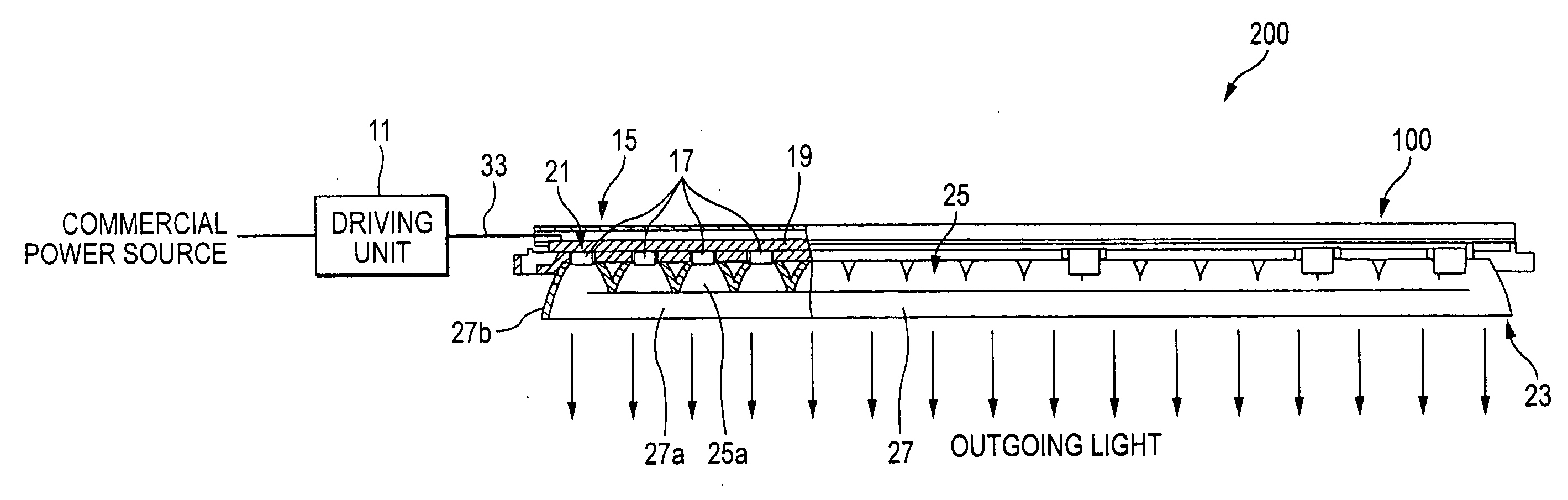
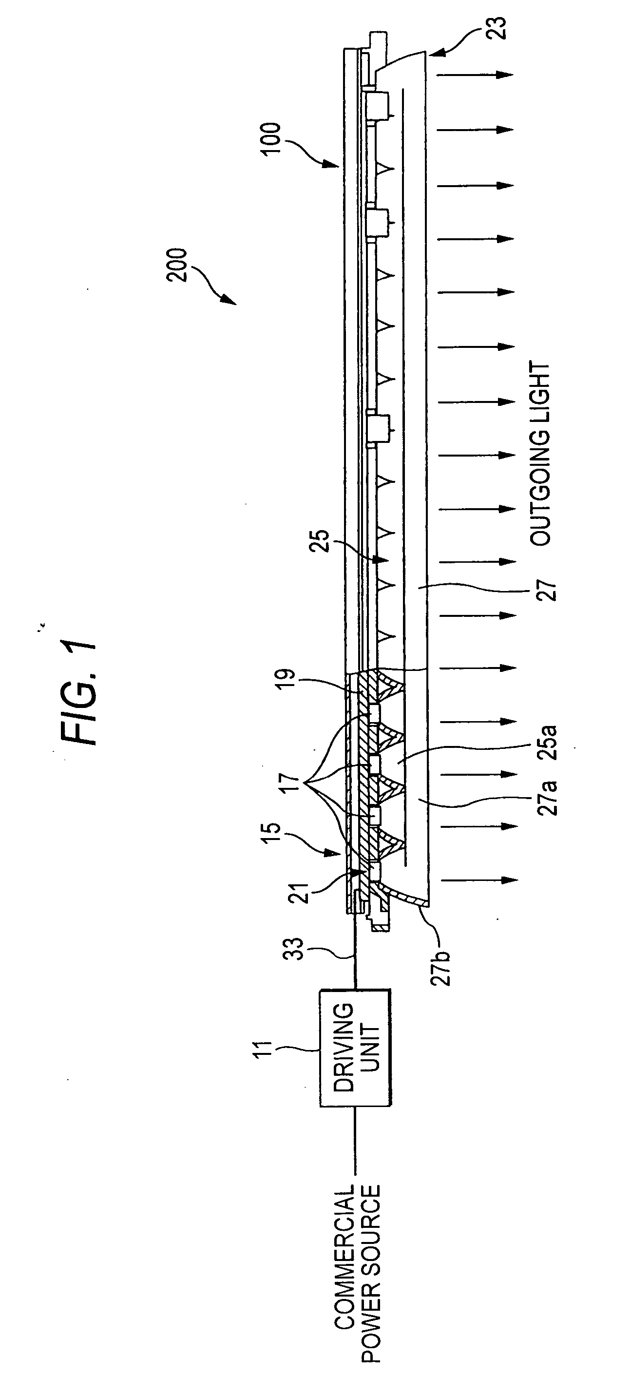
[0084]FIG. 1 is a drawing illustrating an overall configuration of a first embodiment of an illumination apparatus according to the invention.

[0085] An illumination apparatus 200 of the first embodiment according to the invention includes an illumination unit 100 and a driving unit 11.

[0086] The driving unit 11 supplies light emission driving power to the illumination unit 100, and a full-range transformer or the like can be used as the driving unit. The driving unit 11 is connected to a commercial power supply to convert electric power in the range of AC 110 to 220 V / 50 Hz to 60 Hz into a driving voltage of DC 12V (arbitrary voltage such as DC 6V or DC 24V or alternate current may be used) and then supplies the converted driving voltage to the illumination unit 100.

[0087] The illumination unit 100 includes a back plate 15, a light emitting unit 21 having a plurality of light-emitting diodes (LED) 17 arranged in line on a wiring substrate 19 serving as abase, an...

second embodiment

(Second Embodiment)

[0129] Next, a second embodiment of the illumination unit according to the present invention will be described.

[0130]FIG. 12 is a perspective view illustrating an illumination unit whose reflecting surface is formed of a satin-finished surface. FIG. 13 is a cross-sectional view of a reflector member shown in FIG. 12. FIG. 14 is an explanatory drawing showing the illuminance distribution by the illumination unit whose reflecting surface is formed of a satin-finished surface. In the following embodiments, the same reference numerals are attached to the same components as those shown in FIGS. 1 to 6, and the descriptions thereof will be omitted.

[0131] In the illumination unit 300 according to the embodiment, at least one of reflecting surfaces (the parabolic mirror 25b and plate mirror 27b) of the first and second reflecting sections 25 and 27 is formed of a satin-finished surface.

[0132] As a coating process to which the above reflecting surfaces (the parabolic mir...

third embodiment

(Third Embodiment)

[0138] Next, a third embodiment of the illumination unit according to the present invention will be described.

[0139] In the embodiment, there is provided a construction where a wide range of illumination is performed.

[0140]FIG. 16 is an explanatory drawing showing the illumination unit according to the embodiment and the illuminance distribution by the illumination unit.

[0141] The illumination unit 400 of the embodiment is including the plurality of illumination units 100 shown in the first embodiment which are arranged parallel in an array. The arrangement interval between the respective illumination units 100 is set so that the entire illuminance distribution (shown by one dot chain line in the drawing) to which intensities of illumination light components from the adjacent illumination units 100 are adjusted becomes flat.

[0142] According to such a construction, by arraying the plurality of illumination units, a range in which the illuminance becomes uniform ...


PUM


Abstract

To provide an illumination apparatus by which an illumination region having a constant flat illuminance distribution is obtained at high illuminance while electric power is saved and which can extend the irradiation distance, and an illumination apparatus including the illumination unit. An illumination unit 100 using a light emitting diode 17 as a light source is provided with a light emitting unit 21 having a plurality of light emitting diodes 17 on a base 19; first reflecting sections 25 that are provided to correspond to the respective plurality of light emitting diodes on the light emitting side of the light emitting unit and reflect light from the light emitting diodes 17 toward the light emitting side to be substantially collimated; and a pair of second reflecting sections that are arranged on the light emitting side of the first reflecting section and reflect light from the light emitting diodes 17, which is not incident on the first reflecting sections 25, toward the light emitting side to be substantially collimated.

Description

TECHNICAL FIELD [0001] The present invention relates to an illumination unit using an LED as a light source and an illumination apparatus including the same. BACKGROUND ART [0002] As conventional illuminating apparatuses, various types of illuminating light sources such as a fluorescent lamp, an incandescent lamp, and a spot light are used. However, the illumination light from such illuminating light sources includes ultraviolet rays which deteriorates an object to be irradiated or the illuminating light sources has an installation limitation due to generation of heat. In consideration of environmental problems such as the reduction of CO2, a light source is desired to have as small power consumption as possible. Recently, an LED light source which generates a small amount of heat and has small power consumption has attracted considerable attention, and a white LED having high luminance is also provided. Therefore, usage of LED light sources in general illuminating apparatuses is in...

Claims


Application Information

Patent Timeline
Patent Type & Authority Applications(United States)
IPC IPC(8): F21V5/00
CPCF21K9/00F21S4/008F21V7/0083F21Y2105/001F21Y2103/003F21Y2103/022F21Y2101/02F21V7/005F21S4/28F21K9/68F21Y2103/10F21Y2103/33F21Y2105/10F21Y2105/18F21Y2115/10
Inventor HIRATSUKA, TOSHIO
Owner MEERE
Why Eureka
Try Eureka