Illumination device

a technology of a slit lamp and a slit lamp is applied in the field of slit lamp, which can solve the problems of increasing the price and power consumption affecting the reliability of the slit lamp, and short led distan

Inactive Publication Date: 2010-01-07
HON HAI PRECISION IND CO LTD
View PDF18 Cites 1 Cited by
  • Summary
  • Abstract
  • Description
  • Claims
  • Application Information

AI Technical Summary

Benefits of technology

[0013]Light emitted from the light sources 222 travels to the side surface 2113 and is refracted from the side surface 2113 to the shell 224. Light emitted from the periphery of the light sources 222 travels to the upper surface 2111 and is refracted from the upper surface 2111. Some light is refracted from the upper surface 2111 to the shell 224, and some light refracted from the upper surface 2111 reaches the reflective layer 223, to be refracted from the reflection layer 223 to the optical lens module 21. The optical lenses 211 increase brightness of the light sources 222, such that irradiation distance of the illumination device 20 is increased, and rates of utilization are improved.

Problems solved by technology

The large number of lamps, however, increases price and power consumption of the module.
Considerable heat is also generated, which, if not adequately addressed at additional expense, impacts lamp reliability.
Furthermore, since the light-emitting diodes (LEDs) are generally arranged on a printed circuit board having a planar surface, light-emitting range of the LED is usually between 90° and 120° and irradiation distance of the LED is short, making it unsuitable for environments requiring increased illumination.

Method used


Image

  • Illumination device
  • Illumination device
  • Illumination device

Examples


first embodiment

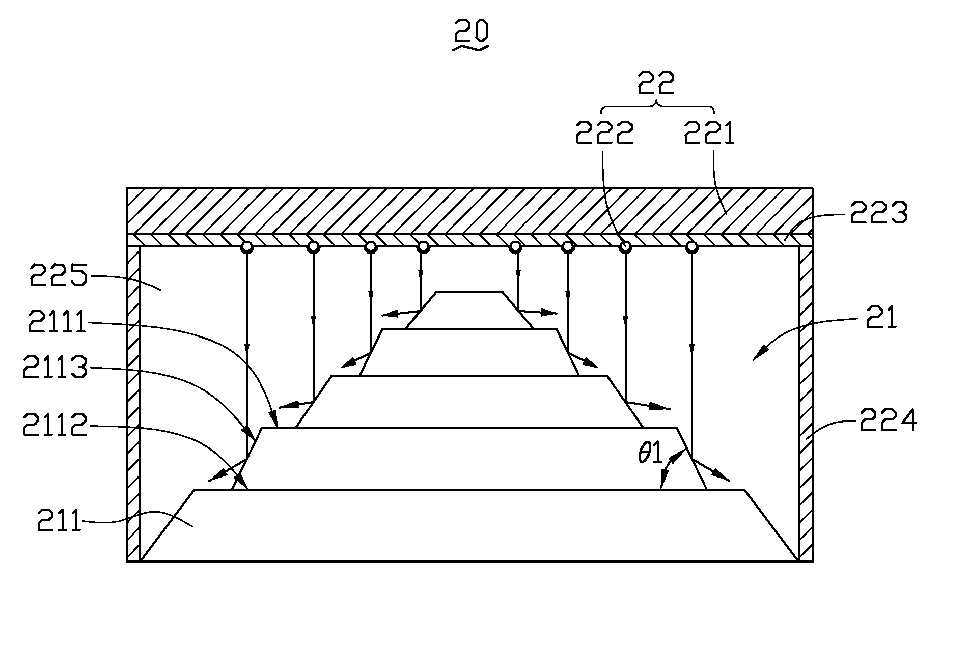
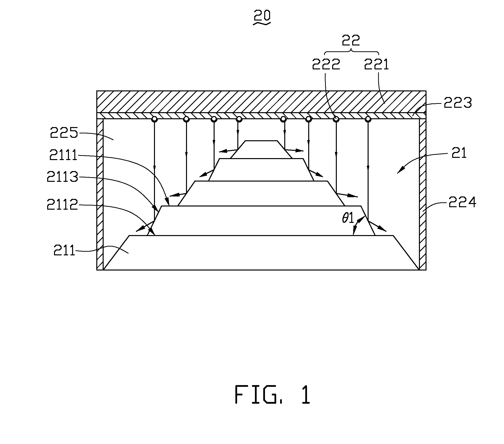
[0009]Referring to FIG. 1, an illumination device 20 according to the disclosure includes an optical lens module 21 and a light emitting module 22.

[0010]The optical lens module 21 includes a plurality of stepped optical lenses 211 superposed one by one. Each of the optical lenses 211 includes an upper surface 2111, a lower surface 2112 opposite to the upper surface 2111, and a side surface 2113 between the upper surface 2111 and the lower surface 2112. The side surface 2113 is a reflective surface.

[0011]The light emitting module 22 is opposite to the optical lens module 21. The light emitting module 22 includes a substrate 221 and a plurality of light sources 222 mounted on the substrate 221. It will be appreciated that the plurality of light sources 222 can comprise a plurality of light-emitting diode (LED) chips, a plurality of LEDs, or a plurality of LED modules, all being equally applicable and remaining well within the scope of the disclosure. A reflective layer 223 is fixed on...

second embodiment

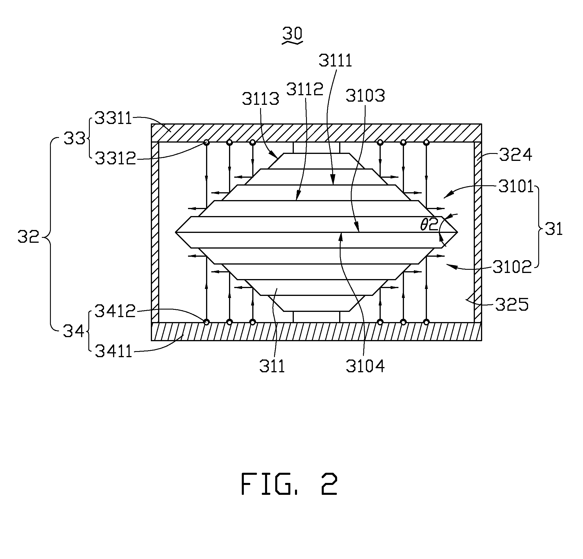
[0015]FIG. 2 is a cross section of an illumination device 30 according to the disclosure, differing from illumination device 20 in that optical lens module 31 includes first optical lenses 3101 and second optical lenses 3102. The first optical lenses 3101 and the second optical lenses 3102 are positioned oppositely to each other. A first bottom surface 3103 of the first optical lenses 3101 is connected to a second bottom surface 3104 of the second optical lenses 3102. A light emitting module 32 includes a first light emitting module 33 and a second light emitting module 34. The first light emitting module 33 and the second light emitting module 34 are positioned opposite to each other.

[0016]The first optical lenses 3101 and the second optical lenses 3102 include a plurality of stepped optical lenses 311 superposed one by one. Each of the stepped optical lenses 311 includes an upper surface 3111, a lower surface 3112 opposite to the upper surface 3111, and a side surface 3113 between...


PUM


Abstract

An illumination device includes an optical lens module, a light emitting module, and a reflective layer. The optical lens module includes a plurality of stepped optical lenses. Each of the stepped optical lenses includes an upper surface, a lower surface opposite to the upper surface, and a side surface between the upper surface and the lower surface. The light emitting module includes a substrate and a plurality of light sources mounted on the substrate. Each of the light sources faces the side surface of each of the stepped optical lenses. Light emitted from the light sources travels to the side surface and is refracted from the side surface. The reflective layer is coupled to the substrate.

Description

BACKGROUND[0001]1. Technical Field[0002]The present disclosure relates to an illumination device including an optical lens module and a light emitting module.[0003]2. Description of Related Art[0004]Known implementations of light emitting modules in an illumination device make use of a plurality of individual lamps to generate light. The large number of lamps, however, increases price and power consumption of the module. Considerable heat is also generated, which, if not adequately addressed at additional expense, impacts lamp reliability. Furthermore, since the light-emitting diodes (LEDs) are generally arranged on a printed circuit board having a planar surface, light-emitting range of the LED is usually between 90° and 120° and irradiation distance of the LED is short, making it unsuitable for environments requiring increased illumination.[0005]Therefore, an illumination device is desired to overcome the limitations described.BRIEF DESCRIPTION OF THE DRAWINGS[0006]Many aspects of...

Claims


Application Information

Patent Timeline
Patent Type & Authority Applications(United States)
IPC IPC(8): F21V1/00F21S8/00
CPCF21V7/0008F21V7/0091F21W2111/00G02B19/0028G02B17/006G02B27/0977G02B19/0066F21Y2101/02F21Y2115/10
Inventor HUANG, SHAN-FU
Owner HON HAI PRECISION IND CO LTD
Why Eureka
Try Eureka